 |
Photo Description
Building a KIS Cruiser Wing
by
Bill Schertz, December, 1998
(Part 4)
Gas Guage Sensor
|
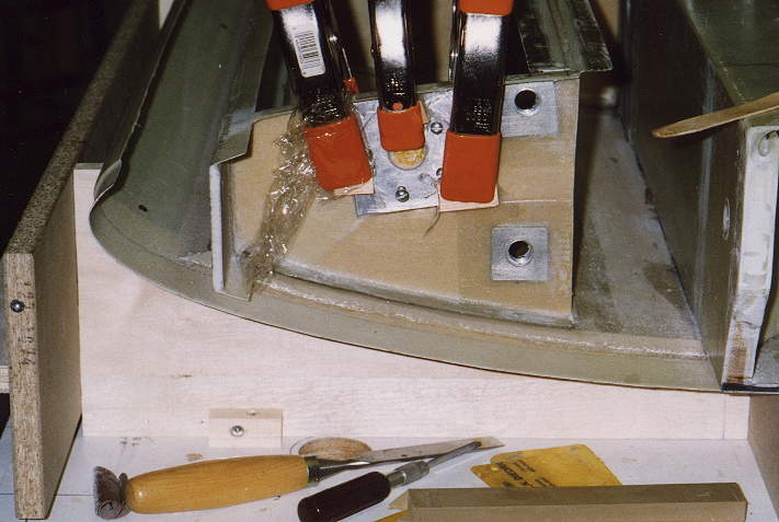
Gas Guage sensor installation -- I finally decided on the Sky-sports sensor, only penetrating the first bay of the tank. This shows the mounting plate being embedded in flox and positioned flush with the skin of the rib.
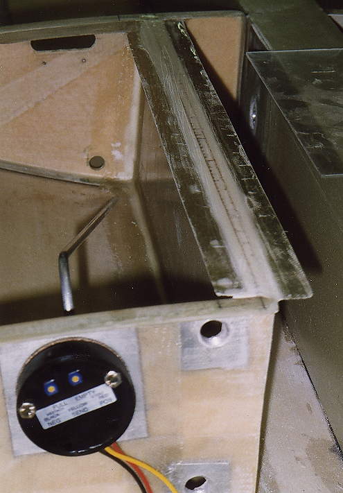 |
View from end with sensor element in place, showing bends to get from bottom of tank to top of tank.
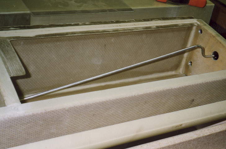 |
This shows the bends more clearly. I used a tubing bender to make smooth bends without collapsing the aluminum tube. If you look carefully, you may be able to see the small hole drilled in the side of the Aluminum tube at the lowest point in the tank, to allow the gas to drain to that point.
Tie-down hardpoint
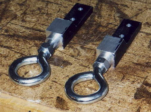 |
Tie-downs are left to the imagination of the builder. Here are mine: I had a section of 1” square Aluminum 4” long machined with a shoulder that was approximately the thickness of the wing-skin, and then drilled and tapped for a 1/2” tiedown ring that can screw into the aluminum. The excess metal below the tapped portion was removed to leave 3/8”, and this was drilled for two 1/4” bolts. The overall idea is to have the shoulder line up with the inside of the wing-skin, and the outer end line up with the exterior wing skin. This is almost the case in the completed wing, perhaps 1/16” low on final assembly. The forces are born by the spar, not the wing skin bond joint.
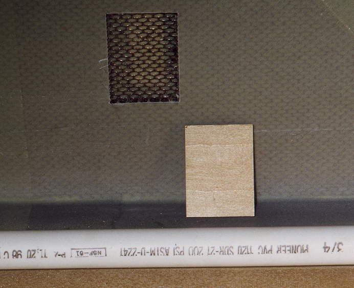 |
A hardpoint in the spar web was cut out, and filled with aircraft plywood, flox, and 2-ply Bid. Photo 23
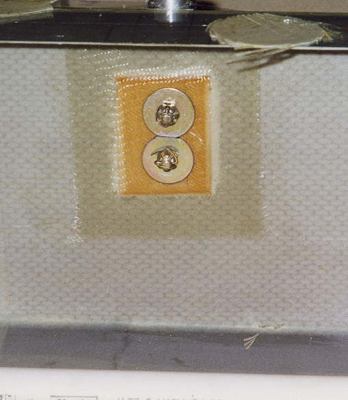 |
The Tie-down is held with castle nuts, with cotterpins installed, since you can’t EVER get back in to tighten these.