Tri-R Technologies
TR-4
BUILDER'S
MANUAL
This Builder's Manual is NOT the official manual
as published by TRI-R Technologies.
HORIZONTAL STAB AND ELEVATOR
IDENTIFY PARTS - (figure 3-1)
-
Inspect the premolded top and bottom horizontal tail skins. Note that each
skin consists of a horizontal stabilizer skin and elevator skin which have
been factory molded in one piece.
-
Identify from the factory labels, the top stabilizer (C104T) and top elevator
(C104ET) skins. The top surface is flat span wise with a leading edge return
or airfoil radius.
-
Identify the bottom stabilizer (C104B) and bottom elevator (C104ET) skins.
The bottom surface has a subtle crown at the center line.
-
Strip off the peel ply from all surfaces and clean away any residue from
the surfaces.
-
Using a felt pen label "top" and "bottom" on both the inside and outside
of the stabilizer and elevator tops and bottoms. Also place arrows indicating
forward (direction of flight) on these parts to avoid confusion when directions
call out "forward face" of some member.
CUT APART STABILIZER AND ELEVATOR SECTIONS
-
Find the scribe lines that will part the stabilizer and elevator on the outside
of each molded piece. These lines run straight across and then around the
elevator balance. Note that on the bottom piece only, that there is a joggle
that will be used to bond a curved piece of fiberglass at a later date.
-
Run a soft pencil along the scribe lines and at the forward part of the joggle
for visibility.
-
Do not cut the elevator skins in half, this will be done in a later step.
Cut along each line very carefully to cleanly separate the elevator and
stabilizer skins. An electric saber saw with fine tooth blade or a hand saw
may be used. (Razor back-saws and hack saw blades in special holders work
well.)
-
When the cuts are complete sand the edges of the stabilizer and elevator
skins with a long block and 80 or 100 grit paper.
-
Place the elevator top and bottom aside.
PREPARE FOR ASSEMBLY
A large square will be handy during the next steps.
-
Measure and mark the center line, then mark B.L. 4 Left and Right,
on both the top and bottom pieces.
-
Measure and mark from the center line, B.L. 20.5 Left and Right, on
both the top and bottom pieces.
-
Measure and mark from the center line, B.L. 48 Left and Right, on
both the top and bottom pieces.
-
Measure 1.25 inches forward of the trailing edge of the skin and layout a
line parallel to the scribe line for the spar aft face location.
-
After marking the locations for the spar and ribs it is a good time to prepare
the areas of the skin for bonding. Take a piece of 80 grit sandpaper and
roughen the areas around the spar and ribs on both the top and bottom skins.
Light sanding is all that is needed to give resin a good surface for adhesion.
Sand the area that lies within 2 inches of each side of the ribs. Sand the
area from two inches forward of the spar back to the rear edge (hinge line)
of the stabilizer.
HORIZONTAL STABILIZER JIG
Using the templates provided in the drawings (TR4-H2) fabricate the jig
components from 1/2 inch plywood or particle board.
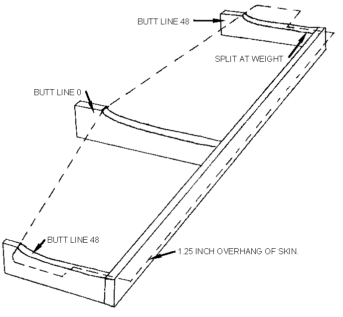
Figure -3, Horizontal stab jig showing skin mounting location.
NOTE - YOU WILL BE BUILDING THE STABILIZER UPSIDE DOWN IN THIS JIG.
-
Prepare a flat table top or other flat surface for assembly with an axial
line roughly 100 inches long.
-
Locate the center of the flat surface (lengthwise) and draw perpendicular
lines marking locations BL-0 and BL-48 left and right. Draw a line lengthwise,
close to one edge of the flat surface, at least to BL’s - 48.
-
Align the back edge of the rib jig pieces with the lengthwise line marked
on the table and the perpendicular lines at BL-0 and BL-48 left and right.
-
Center the jigs on the appropriate BL and bond to the table with bondo or
5 min. epoxy.
-
Cut a good straight piece of nominal 1x2 wood (or equivalent material) 97
and 1/2 inches long and secure to the back edge of the jigs, aligned to be
flush with the contoured surface of the jigs. This will support the horizontal
stab skin at the spar location.
-
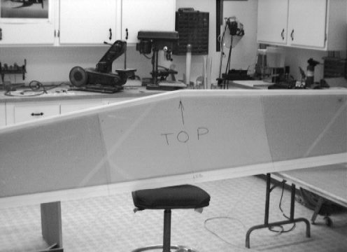
Set the TOP skin into position on the jig, carefully centered, with
the leading edge positioned by the rib template jigs. The rear edge should
overhang the rear of the jig by 1-1/4 inches. The BL-48 rib jigs should
be split down their center by the cutout for the counterbalance area of the
skin. See figure 3-3.
-
Using dabs of bondo temporarily bond skin to jig.
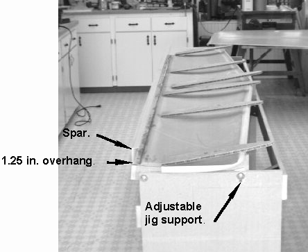
Figure -4: top skin mounted to jig. Spar installed. Ribs ready to install.
PREPARE AND FIT RIBS
- (figure
3-4)
-
Locate the 3/8" prepreg panel with drawn ribs BL-4R&L, BL-20.5 R&L
and BL-48 R&L.
-
Cut with a fine tooth saber saw leaving a little extra for final fit.
-
Sand one edge only, to fit into the skin. The other edge will be sanded to
size during close-out. The outboard side of these ribs will
be lined up with their appropriate lines. (it would be best to mark the ribs
and skin to indicate outboard side)
INSTALL SPAR - (see figure 3-4)
-
Locate the horizontal stabilizer spar (C-123) and remove the peel
ply from the inside.
-
Find and mark the center line.
-
Measure outboard 48" R&L and trim.
-
Clean and sand the top and bottom surfaces for bonding.
-
Align the aft face of the spar to the line that is drawn the length
of the skin trailing edge (previously drawn) and the spar centered on
BL-0.
-
Drill three or four #40 holes through the spar and skin to hold the spar
in place with clecos or screws.
-
Mix a small amount of hysol adhesive and bond the spar to the top of the
skin. Let cure (note: hysol is thin after mixing, so a small amount of flox
can be used to thicken).(note cure times on can)
INSTALL RIBS
- (figures 3-5 and 3-6)
-
Sand the rib sides for pre laming into place and then clean well with acetone
or MEK.
-
Fit BL-4, BL-20.5 and BL-48 ribs to horizontal stab
skin outboard of location lines and glue with 5 minute epoxy to hold
in place.
-
Mix up a small amount of micro for a radius on both sides of each rib
/stabilizer, rib/spar intersection for a fillet.
-
Cut 2 pieces of bid glass 10" wide by the full width of the cloth and prepare
a 2 ply prelam. After covering the prelam with the top plastic, mark and
cut the prelam into 2" wide strips and to the correct length to fit the ribs
from leading edge to spar.
-
Paint on a small amount of resin where the prelam strips will be added.
-
Apply glass to the rib/stab and rib/spar junctions, overlapping each by 1".
(It is okay to overlap the prelam if you end up a little short of material.
Overlap by one inch.) Work out all of the air bubbles and double check everything
before you quit this lay up session.
-
Allow to cure and knife trim any overhangs at the green stage.
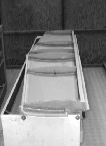
Figure -5: Spar and Ribs installed.
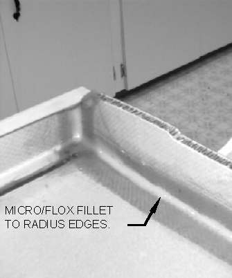
Figure -6: Radius and prelam as shown.
FITTING AND INSTALLATION OF BOTTOM SKIN
Final fit the bottom skin of the horizontal stabilizer to the ribs and spar
by carefully sanding the ribs to size using the bottom skin as a guide. Take
your time and try not to over sand the ribs. The closer the fit the better.
Do the next step before finishing the sanding of the ribs and spar to help
in the fit up.
-
Align the bottom skin to the top along the joggle and drill several #40 holes
and cleco or screw to hold in alignment. Drill several holes along the spar
so that the skin can be screwed or cleco ‘d there also. Make sure the
skin fits and is ready for final installation before continuing further.
-
Once everything fits to your satisfaction drill two small 1/8 in. holes in
each rib fairly close to the top skin. This is to allow the air to neutralize
in the individual bays during climbs and descents.
-
Push down the edges of the exposed honey comb in the ribs with a standard
blade screw driver or similar tool.
-
Make a good amount of micro/flox and fill in the ribs allowing the micro/flox
to mound 1/4" above the ribs.
-
Paint the inside bottom skin with resin where the ribs will contact the skin.
-
Mix a small amount of hysol adhesive and spread onto the spar and joggle.
-
Carefully place the bottom skin into place using the previously drilled holes
for alignment. Once satisfied with the alignment place weights over the ribs
and spar. Drill additional holes along the joggle if necessary and hold with
clecos or sheet metal screws. Clean up any excess resin along the spar and
joggle and allow to cure. Figure 3-7 shows the bottom skin bonded into place
and weighted down.
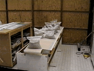
Figure -7, Bottom skin bonded and weighted into place.
-
After curing, remove the clecos/screws and rough sand the holes and fill
with Flox. Don't over do it, your only interest is to bridge the hole.
-
Using a 1/16" drill, make several vent holes along the centerline of the
spar. No more than two holes per bay are required.
PREPARE HINGE ATTACH AREAS
The elevator hinges are mounted on the upper skin, (still in the assembly
jig), since this maintains a straight line. The lower skin aft edge is angled
(peaked at the center of the stabilizer {BL-0}) and the resulting geometric
error would cause binding if the hinges are installed on the wrong (skin)
edge.
-
Measure and mark the pre lam locations as follows, BL-5 to BL-15
L&R and BL-38 to BL-48 L&R.
-
Locate and mark the location of the hinges at BL-6 to BL-14
and BL-39 to BL-47 on both right and left sides.
-
Prepare a 4 ply pre lam, 4 pieces 12" x 3".
-
Measure forward 3/32" from the trailing edge and cut out for the hinge apex
(hinge pin) relief.
-
Place the pre lams on the inside of the top skin, overlapping the
spar at the hinge locations.
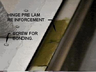
Figure -8, Hinge pre lam reinforcement. Note screws holding wing skin to
spar.
CLOSE OUT TIPS
You will notice that the tip cavities are open and the two surfaces are not
joined at the tip.
-
The open ends are to be faced with a piece of 1/4 foam held in place with
some 5 minute epoxy. This will also aid in aligning the unbonded edges at
the tip.
-
Clean and sand the joggle areas and glass with 2 ply’s of cloth. Stay
inside the joggle.
-
Prepare the corners of the foam close outs for a flox joint. Add the flox.
-
Face the foam with one layer of BID.
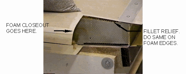
Figure -9, Horizontal stab end showing relief for flox fillet.
ELEVATOR CONSTRUCTION
Construction of the elevator is performed somewhat like the stabilizer except
that it is best to prepare the selected metal parts, prepreg and phenolic
spar pieces, and prepreg ribs prior to starting. Verify that the peel ply
and other debris have been removed front all molded parts used in this assembly.
CUT OUT AND PREPARE RIBS AND SPAR SECTIONS
-
Cut the ribs out of ¼ in. prepreg sheet using the templates supplied.
Make them slightly oversize.
-
Mark the ¼ in. prepreg panel and ¼ in. phenolic to the spar dimensions
shown in figure XX.
-
(A band saw or saber saw is best used for the phenolic.) Cut the pieces out.
Note that the spar is crowned so each piece should be marked "UP"
so the spar can be assembled correctly. The flat edge of the spar is the
top edge.
NOTE - THE ELEVATOR ASSEMBLY WILL ALSO BE FABRICATED UPSIDE DOWN
-
Transfer the center line (from the H/S) to the inner surface of the elevator
top skin (C104ET).
-
Lay the top skin on a flat surface and use small dabs of Bondo to hold in
place.
CUT AWAY THE FOAM IN TRIM TAB HINGE JOINT AREA
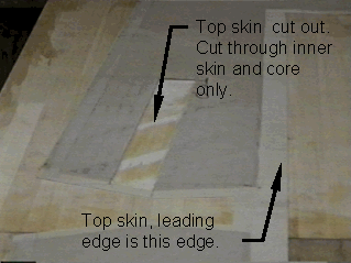
Figure -10, Trim tab cut away.
-
Measure forward of the trailing edge 3 ¾ inches in several locations
on the left of the centerline (this will end up being the right side of the
assembly when it is installed on the aircraft)
-
Draw a line from BL-0 to BL-27 on the inside of the skin.
-
Measure forward (from the trailing edge) 2 ¼ inches and repeat the above
step.
-
At BL-27, using a square make a line perpendicular to the trailing
edge.
-
Carefully cut along the first two lines on the inner skin only.
-
Cut the inner skin off between the lines at BL-27 and remove the foam
in this area.
-
Use the same procedures above to prepare the trim tab area in the lower skin
at this time. Be particularly careful that these cuts are made on the matching
portion of the bottom skin.
SPAR LOCATION
-
Measure aft of the forward edge 1 ¼ inches and draw a line from
BL-48.125 L to BL-48.125 R. This line will locate the forward
face of the elevator spar.
-
Make a perpendicular line at BL-4.5 L&R, BL-20.5 L&R,
and BL-48.125 L&R for the rib locations.
Sand the area within two inches of these lines with 80 grit sandpaper and
remark for easy identification.
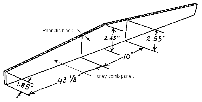
Figure -11, Spar showing phenolic block.
-
Assemble the spar by gluing the phenolic block into the center of the two
spar pieces with 5 min. epoxy making sure that the top edge is straight .
It may help to thicken the 5 min. epoxy with some flox or micro balloons
and to lay the spar down on a flat surface with the center (glued) area on
wax paper. Don't use too much glue and clean up the excess.
-
After the bond has cured, sand both front and back surfaces of the spar.
-
Using several of the ribs as guides and supports, tack glue the spar onto
the skin with 5 minute epoxy with the forward face at the 1 ¼ inch line
and at the tilt angle set by the ribs. Be sure to clean off any excess resin.
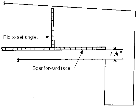
Figure -12
-
Sand the sides of all the ribs and clean with MEK etc.
LAMINTATING SPAR AFT FACE
All the following procedures should be done in one session.
-
Make enough bias cut 2 ply pre lam for a two inch strip 95 inches long.
-
Make a 3 ply pre lam 4 inches by 20 inches long.
-
Mix a small amount of resin and paint a thin layer on the aft face of the
spar and skin where you will be adding the 2 inch pre lam and also the full
surface of the spar between BL- 10 L& R.
-
Mix some MICRO and put a small radius at the aft spar/skin intersection the
full length of the spar, cleaning up any excess.
-
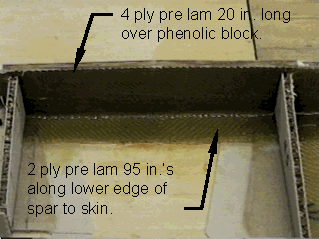
Apply the 4 inch by 20 inch pre lam to the aft surface of the spar from
BL-10L to BL-10R, covering the spar completely and overlapping
the skin by at least one inch spanning the entire phenolic inset and overlapping
onto the outer spar sections. See figure 3-9.
Figure -12, Pre lam on spar aft face, covering phenolic block.
-
Apply a 2 inch wide pre lam from BL-48L to BL-48R on the aft
edge of the spar to the skin, overlapping the spar and skin by one inch and
also over the top of the previously laid up material.
-
To support the spar in its proper position during cure, bond the
BL-20.5 L&R ribs into place with dabs of 5 minute epoxy.
Use tape to hold during cure.
-
Remove all air bubbles with a brush. Green trim any edges of the pre lam
that extends up past the surface of the spar.
-
Verify that the sides of the rest of the ribs have been sanded and cleaned.
-
Place the ribs onto the skin for fit up. The BL-4.5 rib will have
to be cut to allow it to bend to the contour of the elevator cutout. This
is best done by cutting the inside skin with two cuts about ¼ inches
apart and then bending. Ref. Figure 3-11.
Figure -13,BL- 4.5 rib showing bend location and alignment.
-
5 minute epoxy can be used with micro to hold into shape.
-
All the ribs shall be lined up outboard of their referenced lines, the
BL-4.5 ribs with their bent profile being aligned 1 inch in from the
cut edges .
-
Spot glue the ribs into place.
-
Cut off the BL-4.5 and BL-20.5 ribs where they extend past the cut
out foam area for the trim tab, and discard these sections.
-
From the ¼ in. panel make two small spar sections that will go into
the cut out area of the elevator for the trim tab spars. See figure 3-12.
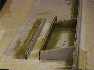
Figure -14, Trim tab spars installed, ribs cut to fit.
-
Judge the height required from the adjacent ribs, keeping in mind that these
spars will be bonded to the lower skin where the foam has been cut away for
the trim tab hinge.
-
Spot glue these pieces to the glass section of the skin tight against the
cut edges of the foam.
-
Using micro make a small fillet on all ribs, and on the inner panel side
of the small added spars (on the sides away from the hinge area).
-
Glass all the ribs, and the filleted sides of the small spars into place
with a two ply pre lam except for the inboard side of the BL 4.5 rib.
See figure 15
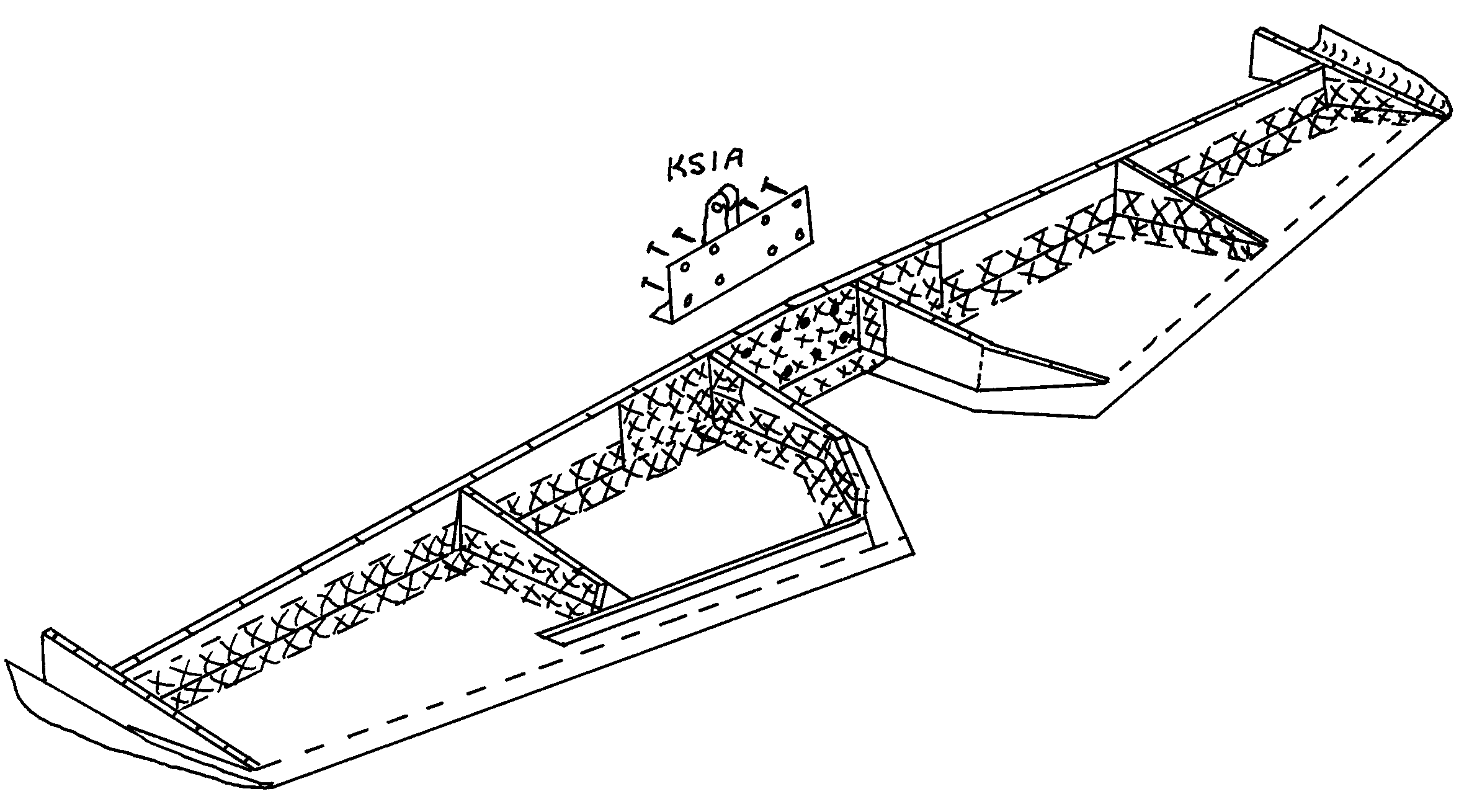
Figure -15, Prelam ribs into place as shown.
-
Take a piece of scrap ¼ inch foam and make bulkheads for the counterbalance
weight areas.
-
These should be securely installed as shown, in the counterbalance areas
about 3.5 inches back from the open end with 5 minute epoxy. Their only purpose
will be to temporarily trap small shot when the balancing step is carried
out later. They need not be glassed at this time. Note that at this time
the forward end of the counterbalances is open. Figure 3-16.
Figure -16, Foam bulkhead.
Figure -17, Ribs and spars installed.
FIT AND INSTALL BOTTOM SKIN
The bottom skin may now be added. Take plenty of time to make sure that the
bottom fits properly on top of the spar, ribs, and trim tab spars. Remember
the foam must be cutout for the trim tab. No doubt some areas will have to
be relieved with a sanding block to permit a good flush fit of the skin at
all the joining edges.
-
Line up the skins for a final time and when satisfied, drill two alignment
holes at the ends of the trailing edge of the elevator for when gluing later.
-
The height measurement from the outside skin to outside skin at BL-0
is 2-3/4 inches and at BL-48 is 2.3 inches.
-
You should set the horizontal stabilizer assembly against the elevator for
a fit check.
-
Prepare the edges of the elevator spars and the ribs for micro-flox joints.
Collapse about 1/4 inch of core along the top edges of the ribs and spars
using a flat edge screwdriver.
-
Mix up some 50/50 micro/flox and fill the resultant channels in the spar
and ribs. Pile the micro/flox an extra 1/4 inch above the glass edges. Put
a very small amount along the top of the two trim tab spars.
-
Apply a flox "bead" about ¼ inch in diameter along the trailing edge
of the elevator.
-
Place the bottom skin in position avoiding sliding and use small screws or
clecos through the line up holes previously drilled.
-
Tape the edges and apply weights to hold everything in position until the
resin cures.
-
Be sure to clean up excess resin especially along spar area.
-
Break the bondo dabs that hold the elevator to the table and remove it for
ease in carrying out the remaining steps. Setting the elevator on its trailing
edge will help do the next steps.
-
Sand the face of the spar and top and bottom skins inside leading edges,
then clean, to prepare for glassing.
-
Fillet with micro/flox making sure the fillet is very small at the phenolic
area. (This is to allow for the correct fit of the elevator horn. It may
be a good idea to fit the horn into position to see how much of a fillet
you can apply.)
-
Prime with resin before installing the pre lam and make sure you work out
any air bubbles.
-
Make a 3-ply Pre lam 5" x 97" to go down the spar face and to the leading
edge of the top and bottom skin, covering all three surfaces.
-
Make enough 4 ply pre lam for 2 - 3" x 12" pieces to go on the inboard hinge
points from BL-5 to BL-17 L & R, overlapping the spar by
one inch.
-
Make enough 6 ply pre lam for 2 - 3" x 12" pieces to go on the outboard hinge
points from BL-36 to BL-48 L & R overlapping the spar by
one inch.
-
Trim the glass when it has cured to a "green" condition.
-
Sand the out board joggles and apply a two ply pre lam closing out the ends
of the elevator.
-
Apply a single ply of bid to the foam bulkhead previously installed at each
end for the counterweight area, overlapping both the top and bottom skins.
CUT TRIM TAB SURFACE LOOSE
-
On the trim tab side of the elevator, measure and mark a line 3 inches forward
of the trailing edge, from the centerline to BL-27 on both the top
and bottom skins.
-
Mark the top of the trim tab. Cut along this line through both skins with
a fine tooth saw, removing the trim tab from the elevator. Do this carefully
so as not to loosen the skin where it bonds to the inboard ribs.
-
Remove an additional 1/8 inch skin from the bottom of the tab to allow for
downward movement.
Figure -18, Trim tab separated from elevator.
HINGING TRIM TAB
-
Clean up the center channel area in the trim tab, and the opened edge of
the stabilizer, and lay in two plies of BID. Do not fillet these areas with
micro (a radius at this point will not leave enough room for the hinge).
-
Using the 12 inch by ¾ inch hinge material. Cut the hinge into two 6
inch pieces and remove the hinge pin so that you call make the pin a ¼
" shorter than the hinge. Replace the pin and lightly crimp the ends of the
hinge to retain the pill.
-
Using the small hinge, make sure it will fit prior to glassing the close-out
ply.
-
Attach the hinge to the top flange edge with countersunk (flat head) rivets
(not supplied) or use countersunk (flat head) #4-40 screws and 4-40 lock
nuts provided in the kit. Locate these holes carefully since both the hinge
and composite flange are quite narrow. The hinge apex should face down and
the cut edges at the hinge line should have about 1/16 inch clearance.
-
Make a trim tab horn of .063 aluminum as show in figure 3-19.
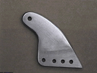
Figure -19, Trim tab horn. Holes at bottom are for bonding.
-
Cut a slot into the trim tab bottom skin close to the inboard edge and inline
with the air flow. Using a small cutter in a dremel or similar tool, cut
through both surfaces of the sandwich panel, but do not cut into the tab
spar or flange.
-
FLOX the horn into place through the slot and the open end of the trim tab.
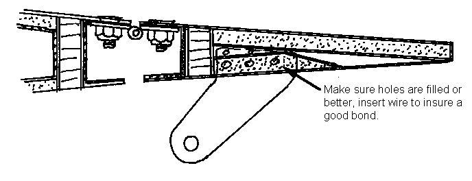
Figure -20, Side view of trim tab horn installation.
-
Close out the open ends of the tab, and the open end of the stab trim tab
cut out, with 1/4 inch foam and two ply’s of BID.
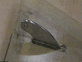
Figure -21, Horn installed into trim tab.
MOUNT ELEVATOR CONTROL HORN
-
Locate the KS-IA pre-made control "horn" and fit it to the spar face, trimming
the lower skin as required. Some trim work may be required on the metal edge
so that only 3/4 inch is cut out of the skin. This part will center on
BL-0 .
-
Using the KS-1A as a guide drill the eight holes with a 3/16" drill bit and
temporarily mount in place with AN3-10A bolts and lock nuts. Ref. Figure
3-18.
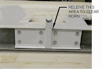
Figure -22, Elevator horn installed.
HINGING THE ELEVATOR
-
Mark the hinge locations on the elevator upper front flange at BL-8
to 16 and BL-39 to 47 L & R .
-
Measure aft of the cut line 3/32 inch and cut out. (this is the hinge apex
relief)
-
Measure and notch the upper rear flange of the stabilizer in the same manner.
-
Take the pieces of MS-20001P5 (1-3/4 inch wide) aluminum hinge strip and
saw 4 pieces 10 inches long. A hack saw or band saw will do the job.
-
Clean-up the hinges with a file or sanding disc.
-
The hinge pins must now be trapped so they cannot fall out due to vibration.
This can be accomplished by removing the pins, cutting them about 1/4 inch
short, replacing them, and crimping the end of the extrusions. (cotter pins
may also be used through drilled holes)
-
Make a precise drill jig from a scrap piece of aluminum or steel angle which
has one leg about 1 inch wide per figure -23.
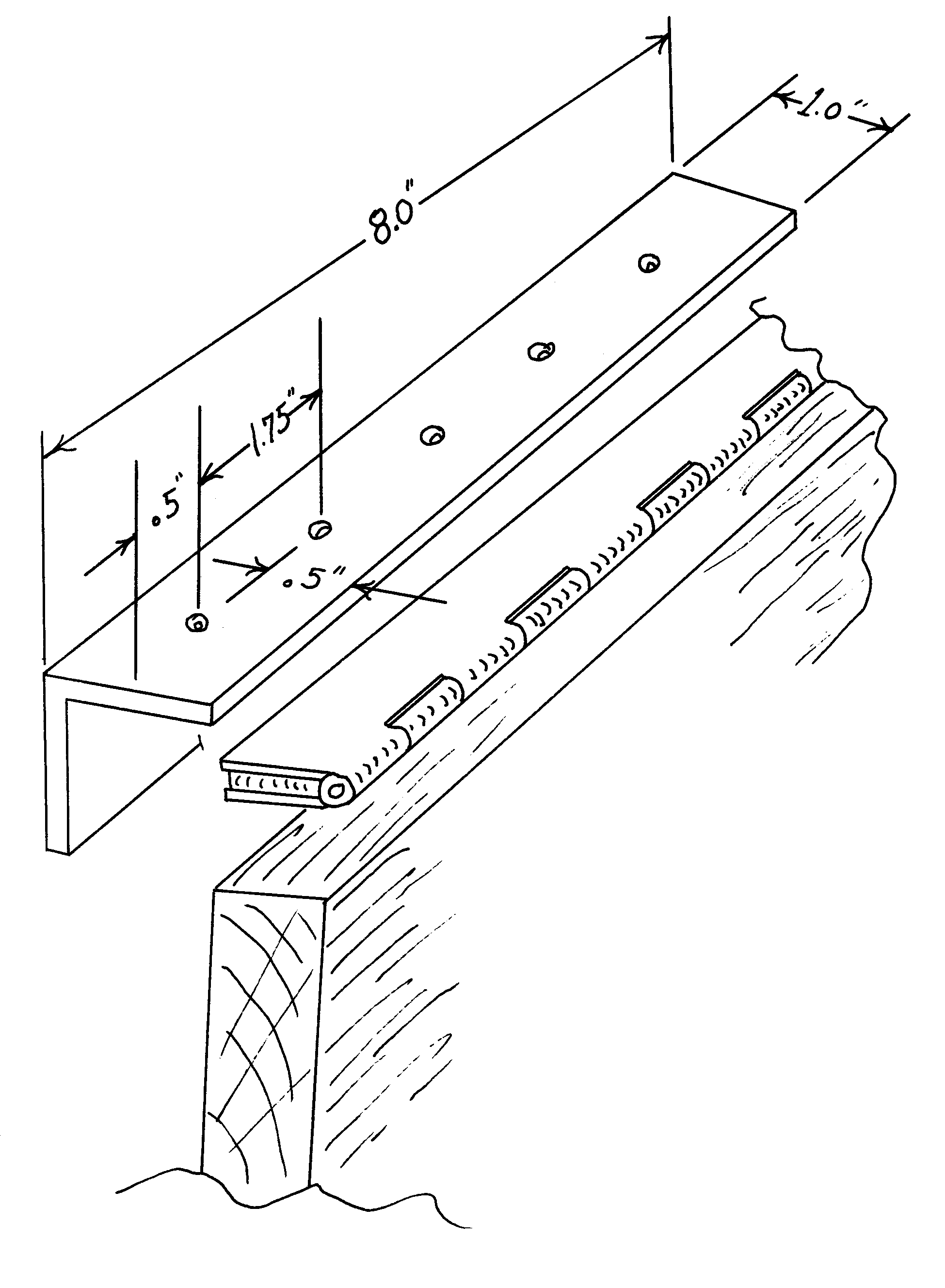
Figure -23, Drill jig for hinges. (also used on wings and rudder)
-
Drill the mounting holes in the four hinges. Accomplish this by clamping
the drill jig angle in a vise. Close the hinge, but space it slightly with
some tape or thin cardboard. Clamp it in the closed or folded condition in
the drill guide with one or two "C" clamps. Drill the holes with a #28 drill
bit. Drill all 4 hinges.
-
The next step is to install the four hinges in their proper positions on
the top stabilizer skin. Place the hinges on the trailing edge of the upper
skin with their pins centered over the recessed edge. Mark their hole locations.
-
Check with a long straight edge to assure that all the hinge pin centerlines
fall on a straight line. If they do not the elevator will not hinge properly
and the problem must be corrected.
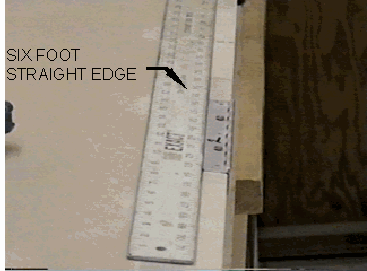
Figure -24, Straight edge check of hinge alignment.
-
Drill #28 holes through the stabilizer flange for the hinge mounting screws,
using the hinge as a drill jig.
-
Countersink from the stabilizer outer surface with a 100 degree countersink
just deep enough that the AN MS24694-S5 mount screws and tinnerman washers
sit correctly in the hole and flush with the skin.
-
With the screws in place secure the hinges to the stabilizer with AN364832A
thin elastic stop nuts over AN960-10 washers.
-
Now place the stabilizer and the elevator right side up on the bench.
-
Determine where the hinge mounting holes should go in the elevator so that
the hinge gap between the two surfaces is minimal. A 1/16 inch clearance
is acceptable.
-
Proceed and mount the hinges to the elevator using the same procedure as
with the stabilizer.
-
The elevator must be able to travel at least 20 degrees down. It will probably
be necessary to relieve the stabilizer lower hinge channel lip where the
elevator horn strikes it. Do not remove material forward of the vertical
web as this will make the stabilizer structurally unsound.
-
This is the time to close the forward end of the elevator balances. First
remove any excess skin that prohibits proper movement of the elevator.
-
Cut two end pieces of ¼ inch thick foam to match the ends of the
counterbalance.
-
Bond the ¼ inch foam to the front end of each balance with 5 minute
epoxy.
-
Shape the foam removing some glass skin for a corner radius.
-
Allow plenty of clearance where the elevator balance swings past the stabilizer.
-
Take a sharp knife and remove foam for flox joints all around the forward
ends.
-
These flox joints must be strong because they will structurally secure the
front end closures and thereby retain the mass balance weight. If they were
to come loose in flight they could jam the controls. Add the flox and cover
the ends with two layers of bid. Trim when "green"
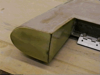 Figure -25, Mass balance close
out
Figure -25, Mass balance close
out
Figure -26, Shaped end of mass balance.
MASS BALLANCING
You are now ready to mass balance the elevators.
-
Make ¾ inch diameter holes in the exposed faces of the outboard ribs.
The holes should be about 2-1/2 inches back from the leading edge of the
balance, but forward of the little foam bulkheads. The weight will
be poured through these holes.
-
Place the stabilizer flat on the edge of a bench and weight it down. The
elevator should hang down about 20 degrees under its own weight.
-
Tape a cup on one or both balances. See figure -27
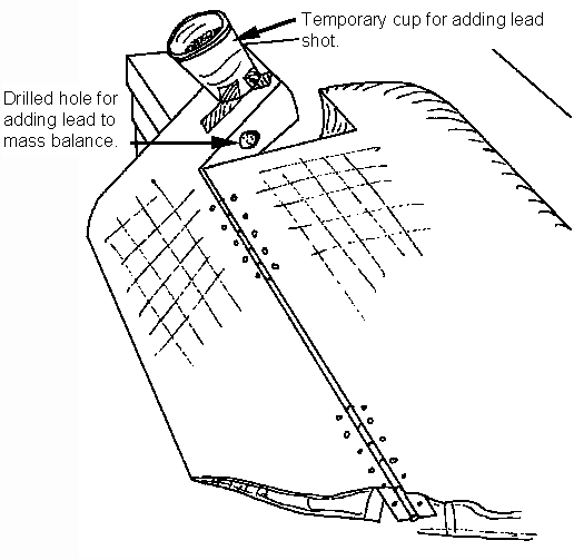
Figure -27, Mass balancing elevator.
-
Fill the cups with lead shot until the elevator surface balances. You will
be adding resin so about 5% of the shot can be removed.
-
Mix the shot with some resin. Stir just a little flox into the mixture.
-
Pour the mixture equally distributed into the left and right balance areas
using the holes in the ribs. Seal the rib holes with tape.
-
Prop the horizontal surface so that the balances are down and the resined
weight will cure in the very forward end of the balance structures.
-
After the weight cures in place check again for balance. The elevator should
be a little overbalanced to allow for paint. If the overbalance is extreme,
excess weight may be drilled out after painting. If the balance is light
add additional shot, resin and flox.
-
Remove the screws that hold the hinges to the stabilizer. Remove the elevator.
Remove the eight bolts that hold the horn.
-
Clearly mark the center line.
-
Using a hacksaw or band saw cut through the center line creating separate
left and right elevator pieces.
When the aircraft tail section is complete you will see that the elevator
needs to be split in order to install or remove it from the aircraft.
Construction of the horizontal stabilizer and elevator assemblies
are completed.