| The KIS Cruiser
Kit, like many other homebuilt aircraft kits,
can be started
with the horizontal stabilizer and elevator kit. Often this
portion
of the kit can be purchased separately and used as a test kit to
determine
if you are really interested in, and have what it takes to build an
airplane.
It also provides an opportunity to see if you are going to feel
comfortable
with the construction techniques.
The elevator top and bottom are molded together with
the stabilizer.
They must be cut into separate pieces along scribe lines formed
into
the molded parts. The details of this process are outlined in the
first
part of the section on the Horizontal Stabilizer. |
|
|
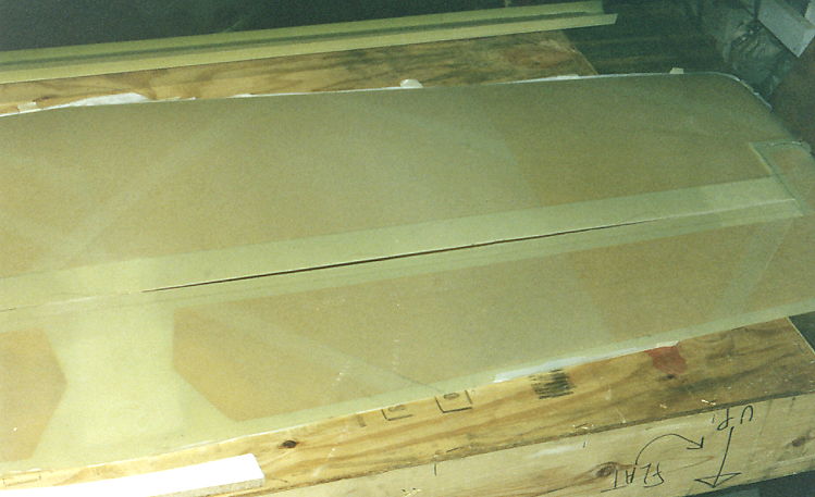 |
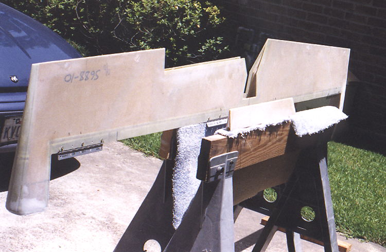
The Horizontal Stabilizer and Elevator come
as two molded parts, an upper skin and a lower skin. There are
score lines on the parts that identify the separation lines for
separating the elevator from the horizontal stabilizer parts.
|
|
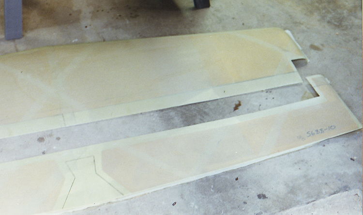
The
separated parts identify the separation points for the division of the
elevator into two parts between the rudder section.
|
|
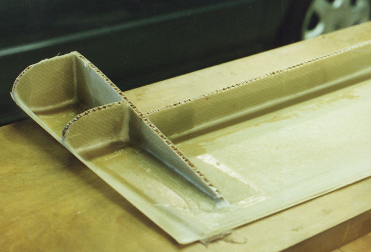
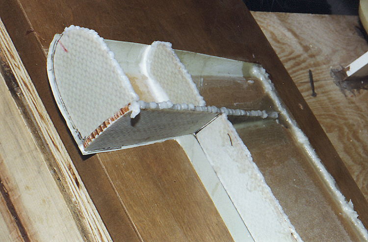
The elevator is prepared by mounting the top to a flat
surface using bondo or 5-minute epoxy.
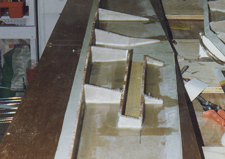
The elevator spar and ribs are prepared and bonded
and glassed in place.
|
 |
The basic spars for the trim tab are also put into
place. (Those of you who have completed their elevators will
notice a major mistake in the size and position of the trim tab on the
this photo. I read the instructions wrong and the trim tab is
much larger than it should be. I caught the mistake after I had
closed out the elevator but before cutting the trim tab out. I
went ahead and cut it to the correct size and made the subsequent
repairs.) |
 |
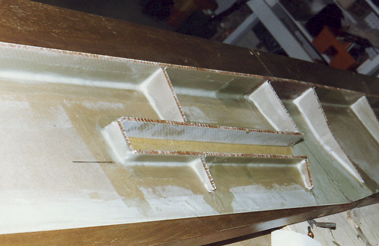
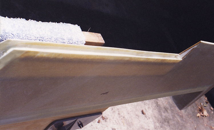
This photo shows a slight modification I made to the
instructions. I closed out the end of the counter weight before
closing the elevator. This gave a very secure chamber for holding
the counterweight lead. I then shaped the end of the counter
weight with foam and glassed it over with two ply bid. Worked
very well. |
 |
|
 |
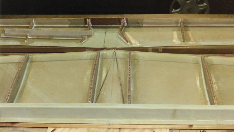
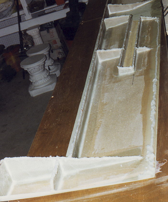
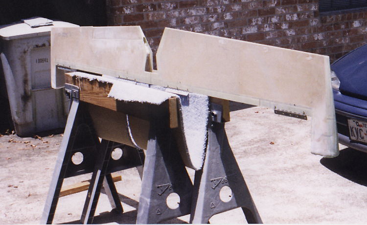
The above photos and left show the horizontal and vertical
stabilizer both ready for closeout. |
This photo, and the one on the right show the space
in
the prepreg and trailing edge of the elevator filled with epoxy-flox.
I smoothed out epoxy-flox to form a uniform bede and closed
out the elevator.
|
|
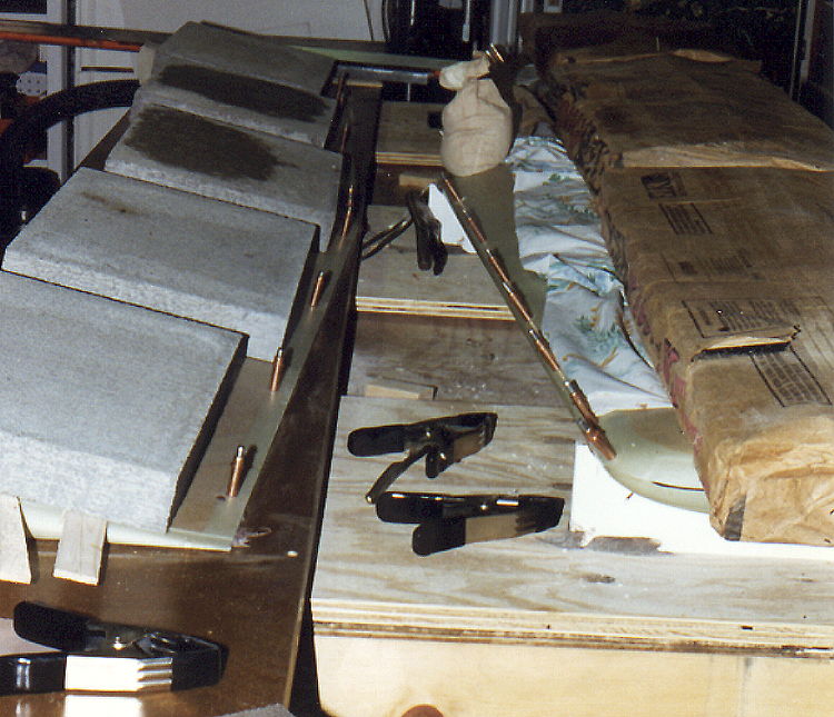 |
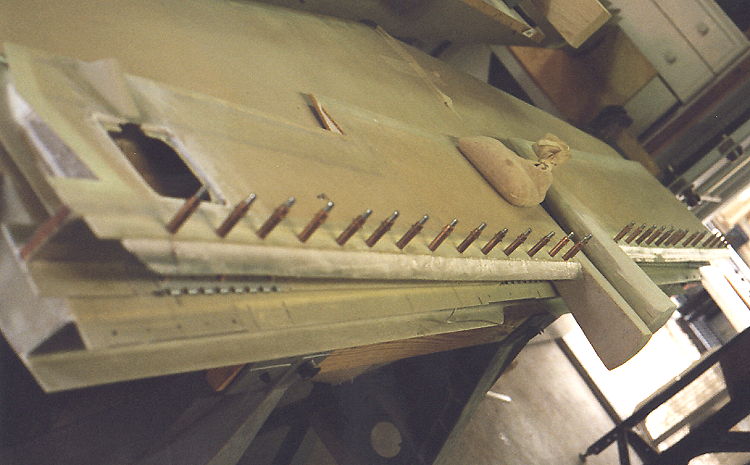
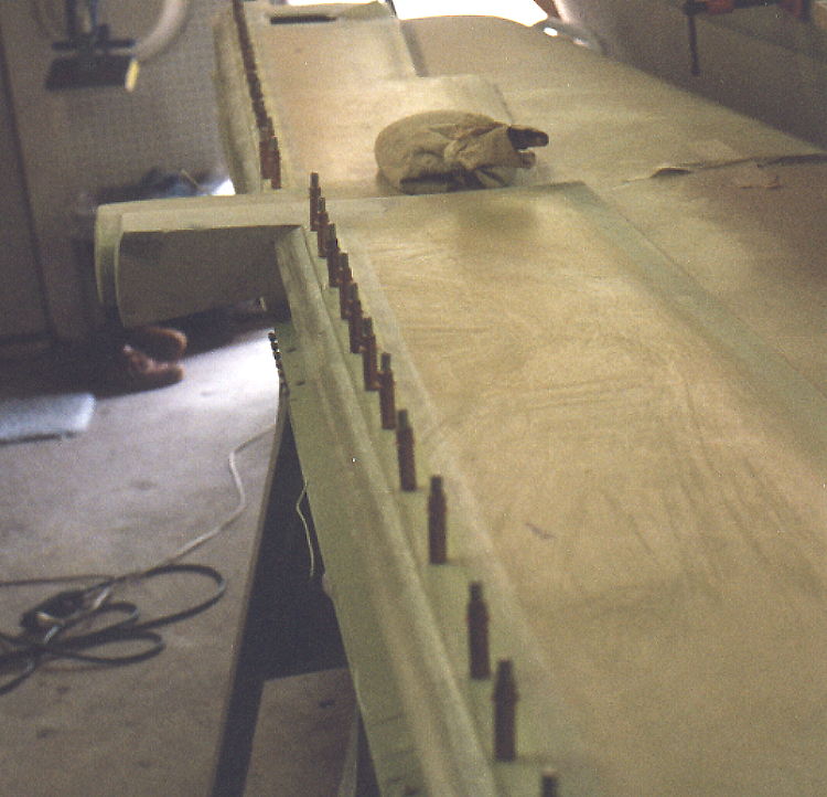
A lot of weight,(a bundle of shingles is very heavy)
clecos, a few shims, clamps and a lot of patience and the elevator and
horizontal stabilizer are close out. (Notice how neat, clean and
uncluttered my workshop is. It may look bad, but it works OK.)
|
 |
 |
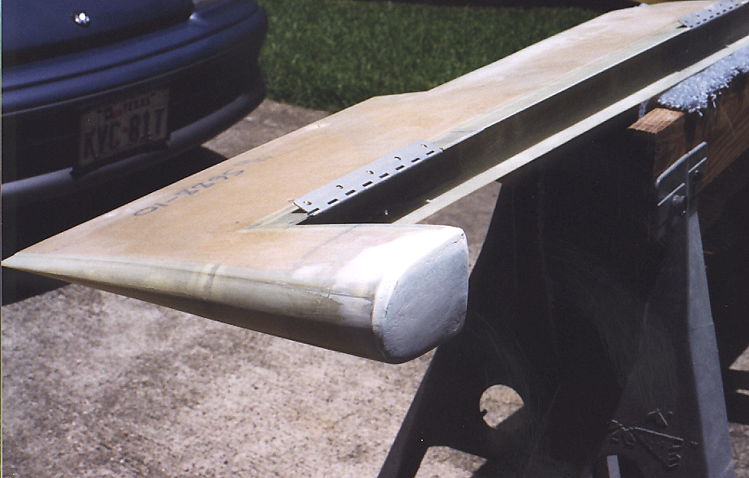
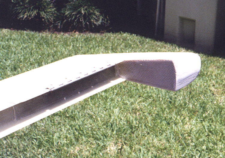
| This view shows the shape of
the elevator counter weight during initial shaping. Some
additional shaping was done prior to final glassing. The result
is very narrow gaps and a very clean look. |
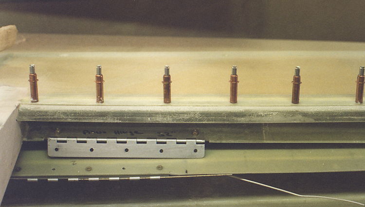
The trim tab shown with the
full elevator. This is the correct size and spacing for the trim
tab. I used a full width piano hinge to join the trim tab to the
elevator. I also used pop rivets centered on each hinge tab to
join the tab. This was taken just before separating the two
halves of the elevator. |
|
 |
|
The inside
edges of the trim tab had to be reinforced with a layer or two of glass
to provide for mounting the hinge for the trim tab.
|
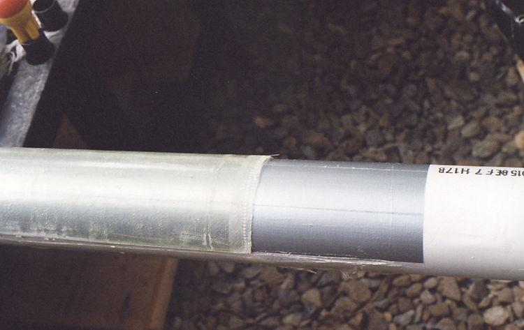 |
I wasn't sure but decided to
make a layup over some 3 inch PVC pipe and see if I could make it work.
I also thought that this would make a good cover for the flap
control tube. Both worked.
Using the good old trusty duct tape, I put several lengths
down the PVC pipe and covered with a length of prepreg glass. A
little peel-ply, some time and I had some nice curved sections of
fiberglass. |
|
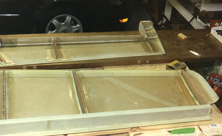
I made two length of the
curved glass. I cut one of them lenghwise into strips about two
and 1/2 inches wide. The photo shows the strip after I bonded into
place using the clecos to hold in place. After bonding, I filled
the edge in, sanded and added a single ply of glass to blend and add
strength. The surface was very smooth and worked out very
well.
|
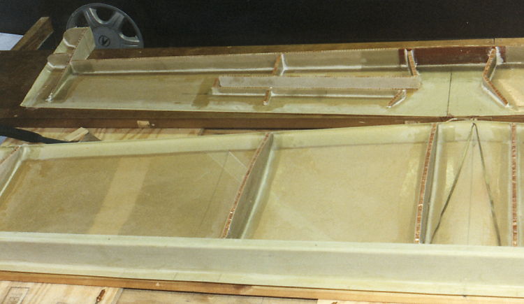
The curved edge is bonded into place and can be seen in these two
photos. The cleco holes were filled and a final layer of glass
added to give a smooth edge.
|
|
|
Once the curved edge was
finished, I checked for proper elevator travel and found that I had to
sand the edge down some to get the required down travel. I also
found that the edge now gave a positive control stop.
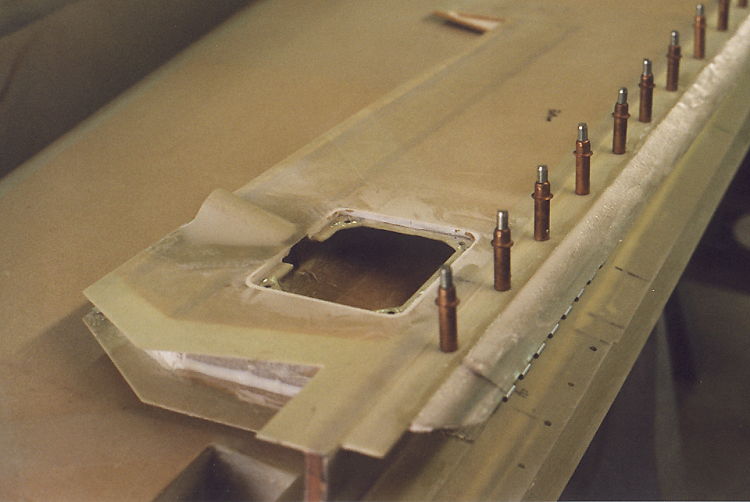
This photo shows the opening for the trim servo and the
fairing for the servo controls.
|
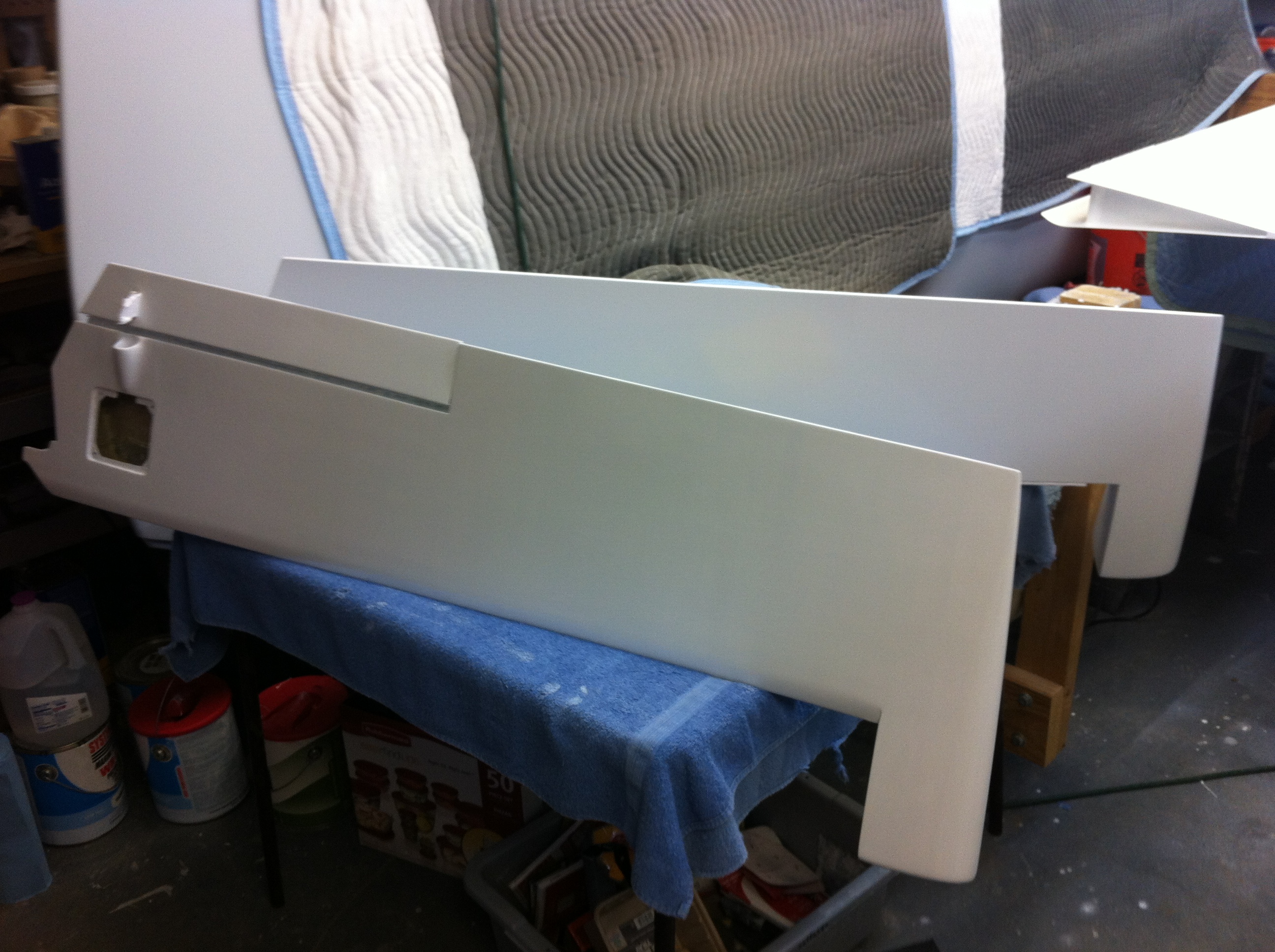 |
The
completed elevator sides have been primed and ready for painting.
They have been balanced with the trim servo installed and should be
very close to a perfect balance once painted.
|
|
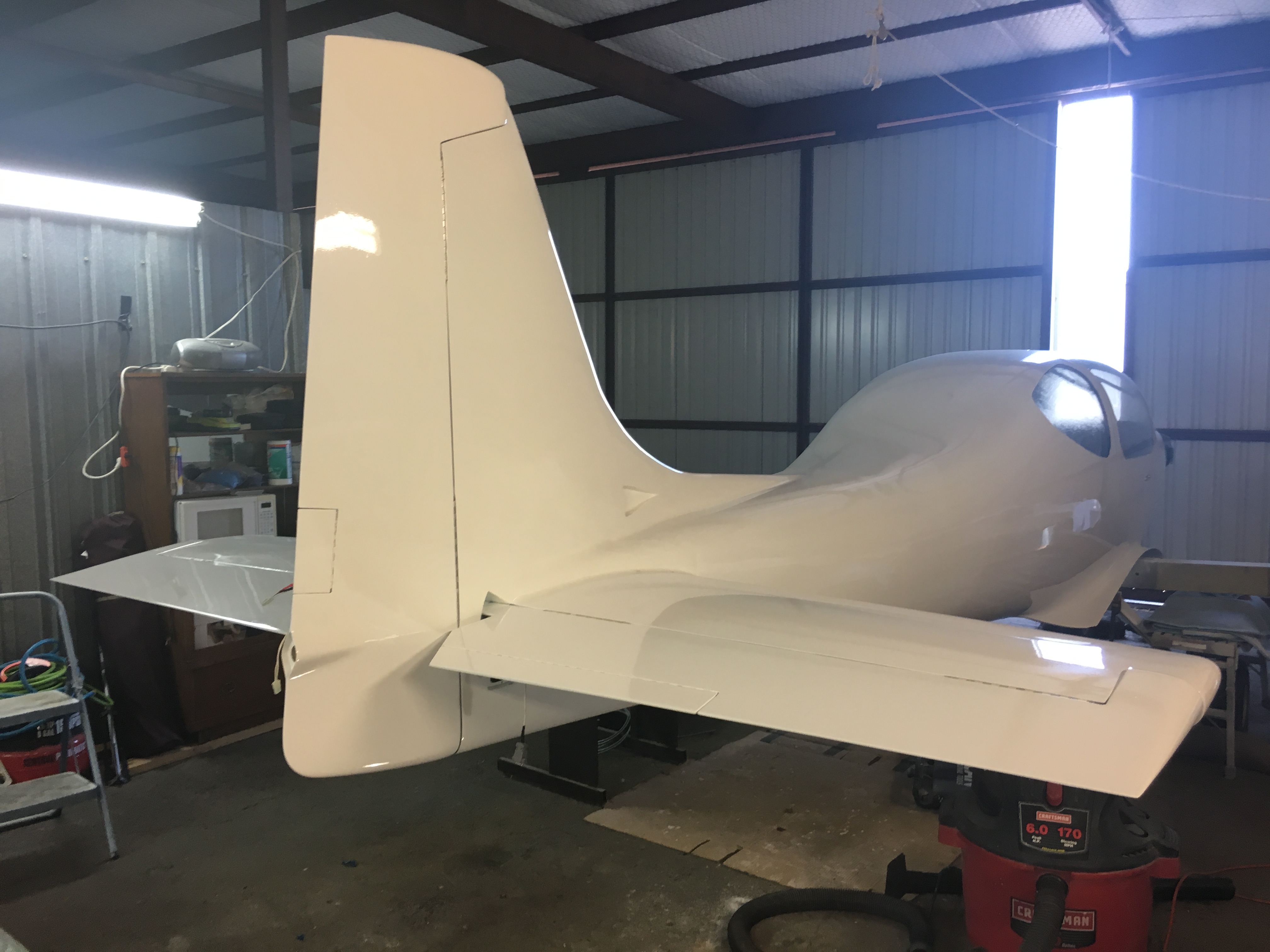
The
elevator has been completed, painted and installed. The control
movement is very smooth and light. The trim tab can just barely
be seen. The hinges are installed with the screw heads recessed
and glassed over to produce a clean surface between the horizontal
stabilizer and the elevator. Extra layers of glass were installed
on the hinge pads to account for the recessed screws.
|