Wing Close Out #1
| The wing close out is probably one of the most intense sessions of the building process. There is much that must be done leading upto the close process and a great deal that must be completed in a short period of time. There are something over 1000 square inches of surface area that need to be fully covered with adheasive prior to the close. It's not a difficult process but once started has to be moved to completion without stopping or the initial adheasive will setup and start curing before you can get the wing closed. We started about 10:30 in the morning and by 12:15 were completed with the loading of the weight. The photos below show much of the advance work that had to be done upto the final load of sandbags and cinder blocks. | |
| PS: This is the first set of photos taken with my new Sony Digital CamCorder using the photo option. They came out really well considering no flash was used in a normally lighted garage. These have been further compressed to make the resulting file as small as possible for web use. Double click on any photo for a larger display. | |
 |
The wing bottom is finally ready after my first attempt at sealing the fuel bay area had to be redone because the initial coat of Jeffco 9700 cured on me before I could get the second coat on. I waited a week to sand it down and put on the needed two coats of sealant. The Jeffco is great stuff but must be mixed in rather small batches and applied quickly or it will setup in the pot. The working time is only about 15 minutes. The cure is quick and the surface is smooth. |
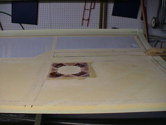 |
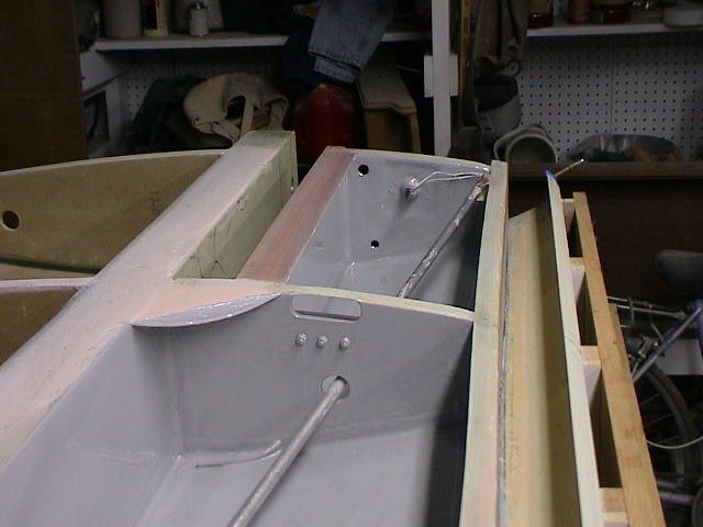
This shows the access panel along with the inner fuel bay bottom. In the right lower corner of the fuel bay you can see the fuel/water drain at what will be the lowest point in the fuel tank. |
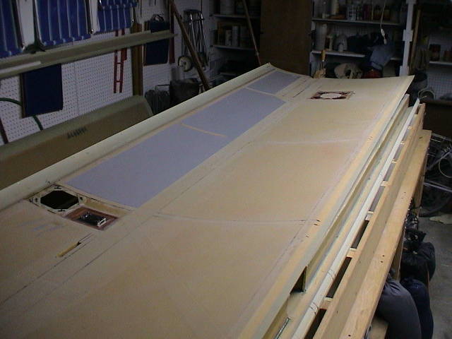 |
Here is a clear view of the lower wing skin which shows
the access panels, fuel bay and sanded areas for close out. The
lower skin is now ready for closure.
The first part of the close process was to wet out the sanded areas with adheasive between the lines shown. |
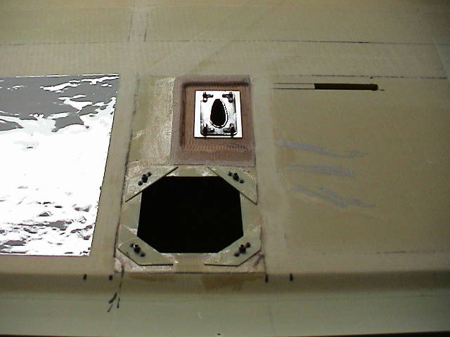 |
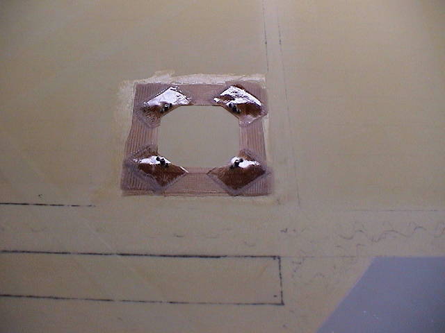
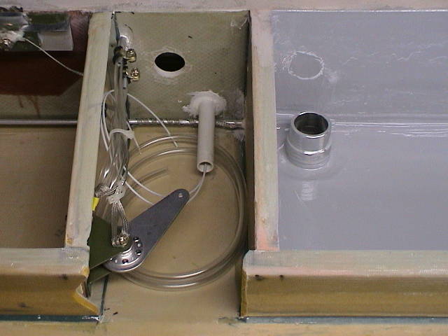
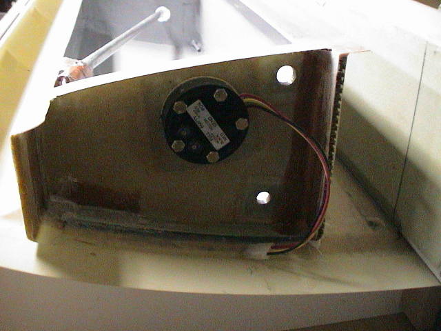
This shows the access opening for the aileron idler arm and the pitot tube. The area above the access opening is the bottom mount for the pitot tube. This was installed in a hard point glassed into the wing. The tube is shimmed under the upper part to level the tube into the relative wind. The small slot to the right of the pitot base is the opening for the retractable tiedown. |
 |
|
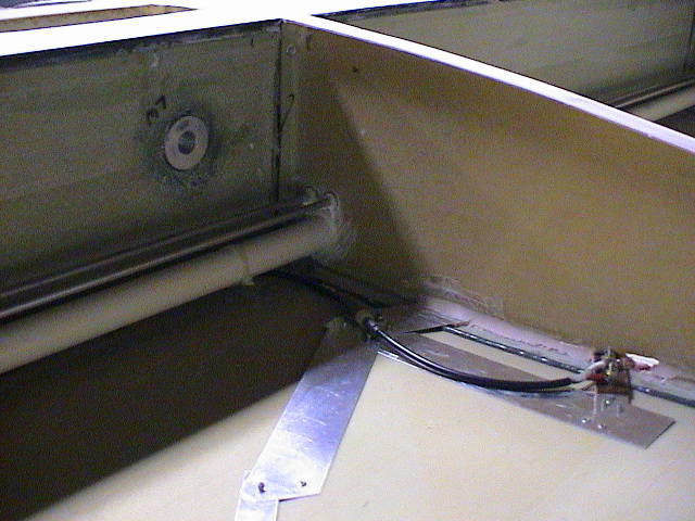
| The photos above and below show the pitot line and electrical conduit (upper left), spar bolt access panel (upper right), Navigation antenna installed against upper wing skin (lower left) and retractable wing tie down (lower right). Note the braided ground line which runs from the fuel bay filler to the vent line, elevator idler arm, tiedown, and ultimately all metal ponts on the wing before return to a common ground point. | |
 |
|
 |
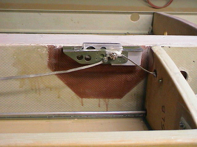
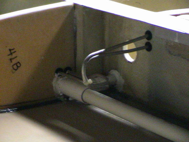
This photo shows the fuel inlet which has a ground wire attached an runs to the outside of the fuel bay, connects with the vent line and then to the idler arm. It runs back and over to the wing tiedown. Inside the opening with the elevator idler arm you can see the electrical wiring for the pitot heater along with the pitot and static lines. The flexable pitot lines are already permanently attached to the aluminum lines through the wing. The tubes are long enough to extend out the base for installation. A tie point is provide for keeping them clear of the control arms. |
 |
|
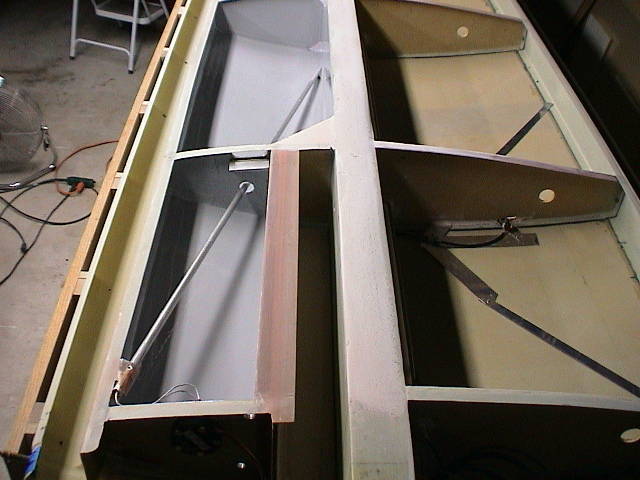
| These shots show the completed and sealed fuel bays. The (upper left) photo shows the fuel level tube running though the first two bays. You can also see the vent line between the first two bays along with the openings for the fuel lines. The (upper right) shows the full view of the inside wing bays with nav antenna and fuel bays. The (lower left) shows the fuel level sensor connection. One important point to remember is to ream out the fuel connection openings after sealing and before closeout. The (lower right) shot shows the slosh valve between fuel bay one and two. | |
 |
|
 |
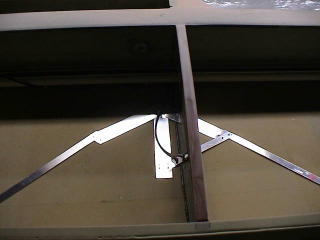
This shows the connection for the navigation antenna. I am using the Archer antennas for all my installations. The are inexpensive and foolproof. I cut an opening in the rib to slide the side of the antenna arms through. The gap is then filled with epoxy filler and the cable mounted. the wings of the antenna are simply pop riveted to the wing skin. This allows the antenna to be set in the optimum open position. |
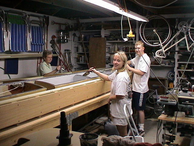 |
Here is my close out team with yours truely out of the shot. My wife, daughter and her long term future significant other (Nope!) were my only crew. They did a great job and painted on a wetting coat of adheasive on all surfaces before I laid down the thicker bead of adheasive / flox required for gap filling and strength. The pre-wet of both the bottom wing skin and the spar/ribs made the process much smoother. |
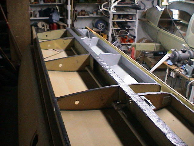
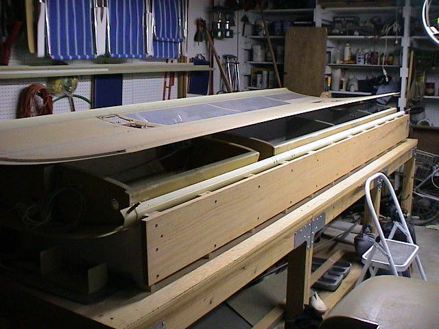
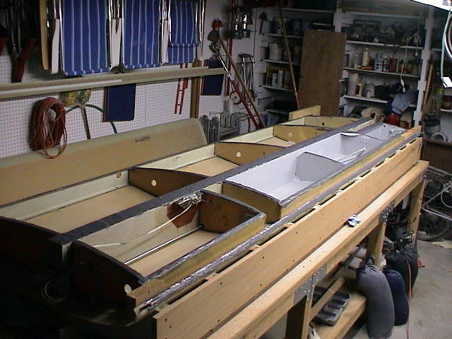
| The next two shots show the wing just before the skin bottom was placed into position. The adheasive is a dark gray and can be seen on all surfaces. I put on a very liberal amount and can only hope that is was enough/not too much. It thickened well and with the prewet done smoothed out well. Only time is will tell if the fuel bay sealed out completely. The joints looked fairly good after the closeout. Some excess was evident only on the inside spar area. | |
 |
|
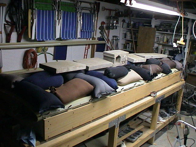 |
Well...it is done. Almost a thousand pounds of total weight is spread over the entire wing with concentration on the areas over the spars and the ribs. I was not too happy with what I could see of the squeeze out at the front spar. There seemed to be a gap at the leading edge of the joint and that may prove to be a problem. The opening is too small and long to get any sealant to. Time will tell. |