 |
 |
KIS Cruiser – Control Stops
Ray Clegg
To show the way we have installed control stops.
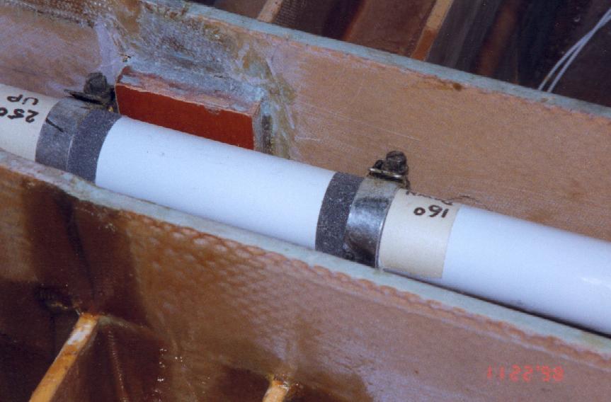
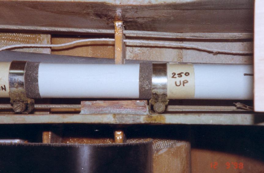
Elevator
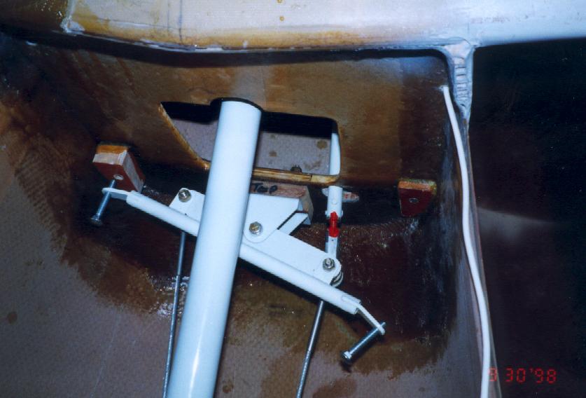
Jubilee (worm drive) clamps have had flat faces brazed onto the worm gear. They are clamped around the elevator push rod. A Tufnol block is epoxied and bolted to the sidewall of the center tunnel just behind the front seat. The clamps are very easily adjusted to give required travel.
|
|
Rudder stops
These we placed on the rear bulkhead by clamping a bar across the top of the rudder horn with adjustment bolts that stop against Tufnol blocks. The disadvantage is that the rudder cables can be loaded by excessive foot pressure on the pedals and adjustment in the completed fuselage is not easy.
 |
 |
 |
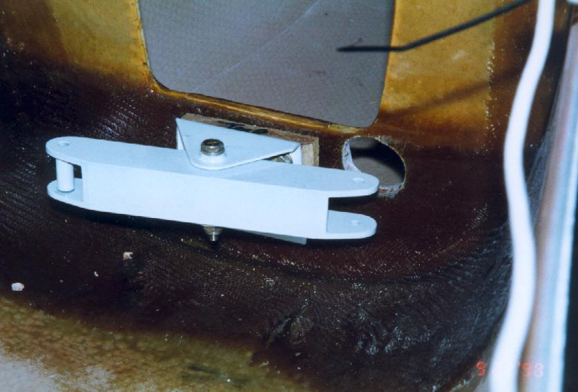
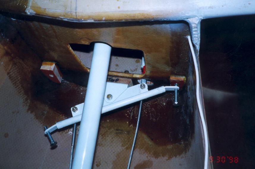
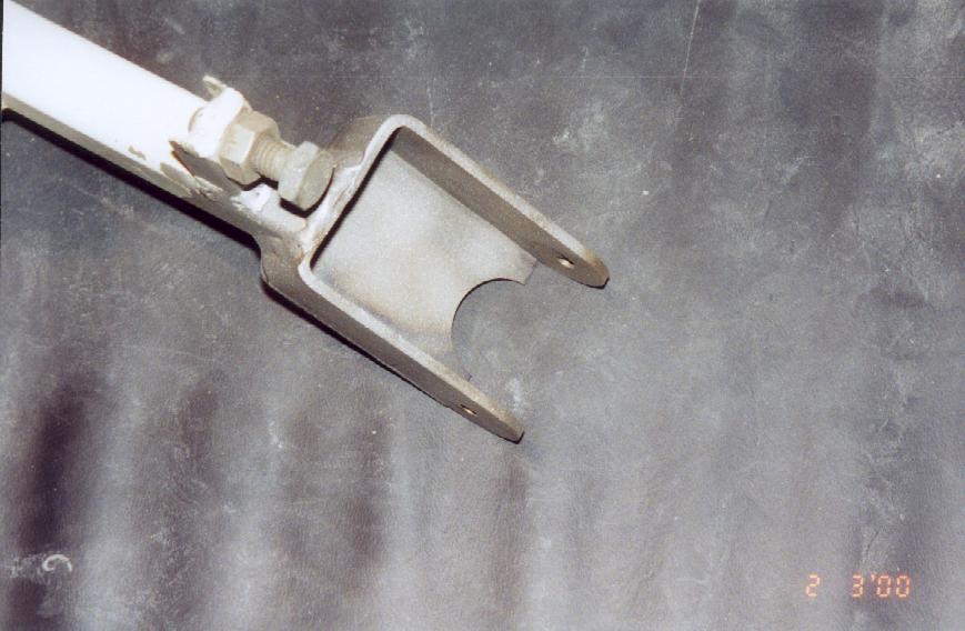
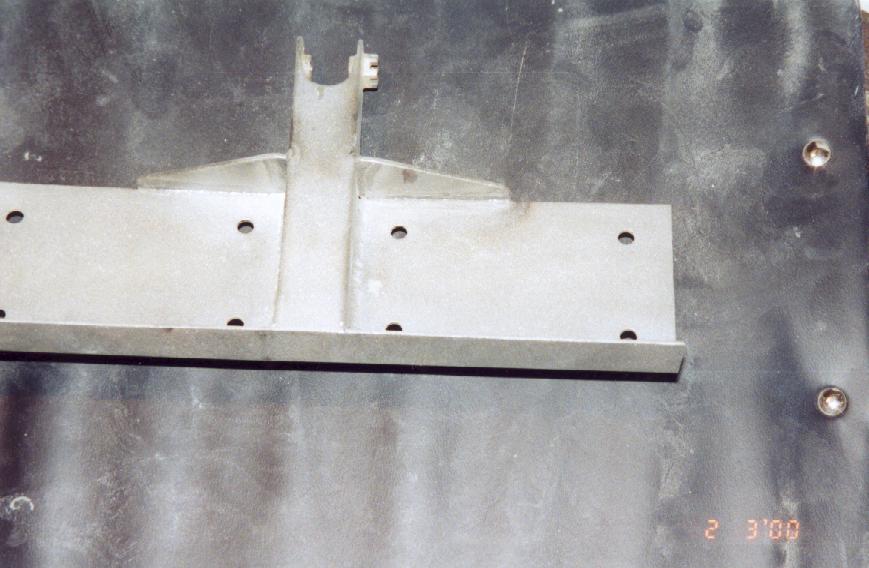
Aileron stops
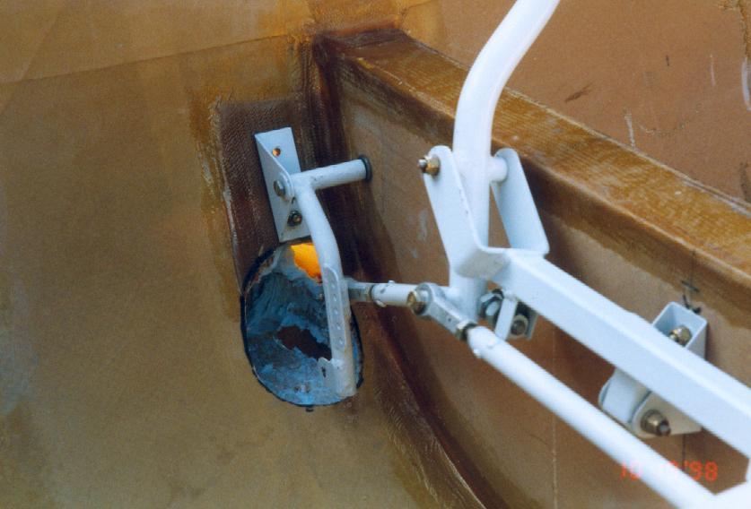
A small bracket was welded to the underside of the inter-stick link to carry adjustable stop bolts. The advantage is the ease with which they can be reached and the load is taken on the sticks and not the aileron push rods.
 |
 |
The photographs also show the modified arms attached to the fuselage side to link the aileron push rods. The original method as detailed in the build manual did not appear to provide the correct geometry
Recent photographs show a modification to the stick attachment, which we were made to carry out by the PFA. They felt it was possible to twist the yoke attachment and so we had to weld a plate across the two arms to prevent that happening. The photograph shows clearly the aileron stop bolts.
 |
 |
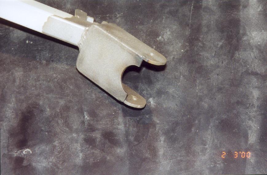
Another modification we had to carry out for the PFA was to weld additional gussets onto the elevator horn.
 |
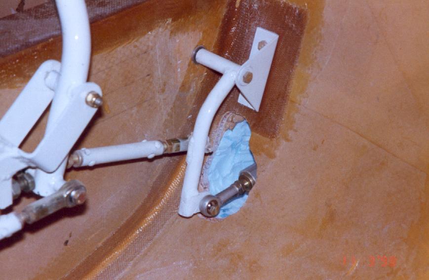
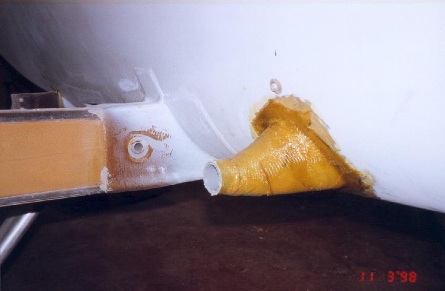
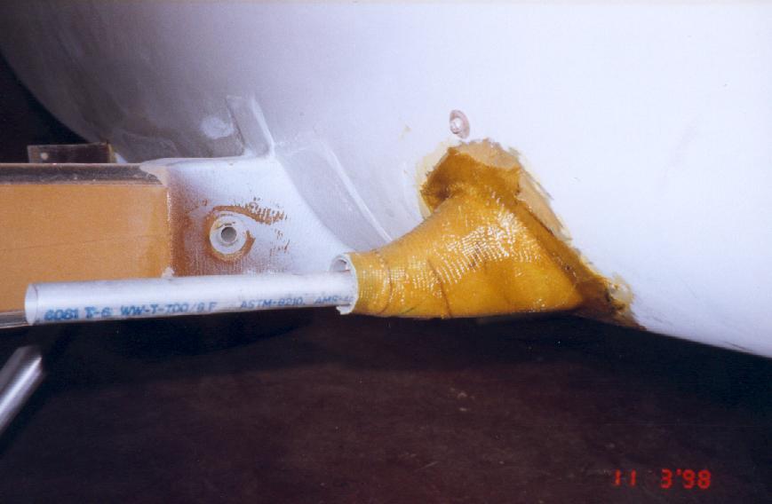
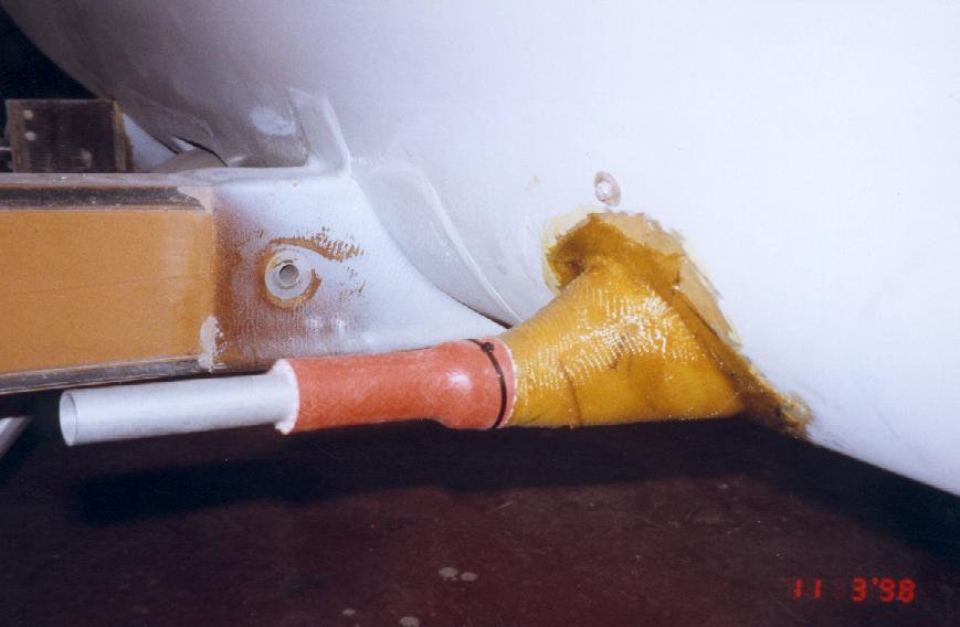
If you wish to prevent draught through the openings in the fuselage side for the aileron tubes a method is shown. A funnel shaped glass fiber opening, which fits closely inside the wing fairing, is constructed. Aeroquip firesleeve is attached to the opening with tie-wraps. The inner fleecy lining to the firesleeve provides a friction free and draught free seal around the aileron push rod.
 |
 |
 |