Tri-R Technologies
TR-4
BUILDER'S
MANUAL
This Builder's Manual is NOT the official manual
as published by TRI-R Technologies.
FUSELAGE
Quick Links to Wing Assembly Sub-Sections:
SPAR
PREPARATION
LEVELING
AND FIXTURING
SPREADER
STICKS
TEMPORARY
FITTING OF THE FUSELAGE TOP
FIREWALL
FIREWALL
FRONT FACE
ADDED REINFORCING IN FIREWALL AREA
STATION
139.5 BULK HEAD
STATION
180.5 BULKHEAD
MAIN
SPAR AND OUTBOARD SPAR PRE ASSEMBLY
REAR
SPAR
MAIN SPAR LOCATION AND INSTALLATION
POSITIONING
SPAR
MOUNTING LAMINATIONS
MAIN
GEAR BOX REINFORCEMENT
SEAT
FRONT BULKHEAD & CONTROL MOUNT
FUSELAGE
BELTLINE
CONDUITS
FRONT SEAT BACK ASSEMBLY
REAR
SEAT BACK INSTALLATION
CONTROL
CONSOLE - FRONT SEAT AREA
ELEVATOR
IDLER BELL
CRANK
SEAT BOTTOM ASSEMBLY
FRONT
SEAT
REAR
SEATS
FRONT
FLOOR ASSEMBLY
STICK
LINKAGE ASSEMBLY
FLAP
HANDLE ASSEMBLY BRACKET
AILERON
IDLER INSTALLATION
FLAP ACTUATION TORQUE TUBE INSTALLATION
RUDDER
IDLER LEVER INSTALLATION
HORIZONTAL
STABILIZER
INSTALL
RUDDER POST
ELEVATOR AND PUSH/PULL ROD
INSTALLATION
RUDDER CABLE ROUTING AND
INSTALLATION
MAIN
GEAR INSTALLATION
BRAKE
LINE INSTALLATION
FIN
RIGHT HALF INSTALLATION
INSTALL
LEFT FIN HALF
HANGING
RUDDER
INSTALLATION
OF FUSELAGE TOP
BAGGAGE
AREA BACK PANEL
DOOR
PREPARATION
WINDOW
INSTALLATION
DOOR
LATCH ASSEMBLY
MOUNT
DOORS
LATCH
PLATE INSTALLATION
AIR
STRUT INSTALLATION
REAR
WINDOWS
INSTRUMENT
PANEL
WINDSHIELD
MAIN GEAR BOX
REINFORCEMENT
The primary reinforcement of the landing gear "box" area is the multiple
layers of BID applied in the high load areas. These are integrated into the
rear seat front bulkhead which is bonded to the center of the main gear box.
-
Fit and tack the bulkhead into place on top of the landing gear recess.
-
Fillet the edges of the bulkhead.
-
Make up Two, 2 inch wide, 2 ply BID tape and apply to each side of the bulkhead.
-
Apply 10 layers (two sets of 5 ply) in the area for the gear mounting bolts,
overlapping up the sides of the fuselage wall and the faces of the seat bulkhead
as shown on figure XXX. Stagger the overlaps of these two sets of plies slightly
to taper the edges.
SEAT
FRONT BULKHEAD & CONTROL MOUNT
-
Cut the front seat forward bulkhead from the supplied flat panel material,
cutting to the outline provided.
-
Insert 1/4 inch plywood hard points as per figure XXX and cover with two
ply bid. A minimum of one inch overlap.
-
Bond the bulkhead into place with 2 ply BID on both sides at STA. 31
(30). Make sure the bulkhead is square in the fuse and is vertical
in alignment.
-
Tack in place a strip of laminate 2 inches wide, on the top edge, forward
side of bulkhead 31. This will form the support for the front seat bottom,
at the front of the seat bottom.
-
Make enough 3" wide prelam strips to bond the inside and top edges of this
support strip. Fillet the inside edge and round and fill the top edge to
give a smooth surface for the pre lams to form and bond too.
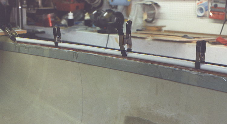
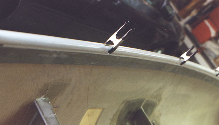
FUSELAGE BELTLINE
CONDUITS
Two sections of plastic tubing shall be bonded to the fuselage in the
''belt-line'' area providing a conduit for antenna coax and electric lines.
This also provides added stiffness along the edge of the cockpit opening.
-
Use the supplied PVC tubing, roughen and tack in place from station 24 to
station 95 with dabs of 5 minute epoxy.
-
When the tubing is secured in the desired location, fill in the edges on
each side of the tube with dry MICRO paste and overlay with 4 ply BID tape
full length. Allow a generous overlap in the bonding areas, 1 inch if possible.
Green trim any overhanging BID in areas where it might interfere with mounting
the top skin. Review figure XXX for approximate location of the tubing and
bonding BID. This tubing should be installed before any other structural
bonding will limit access to this location.
Figure 131-133: Electrical Conduit Installation
 |
 |
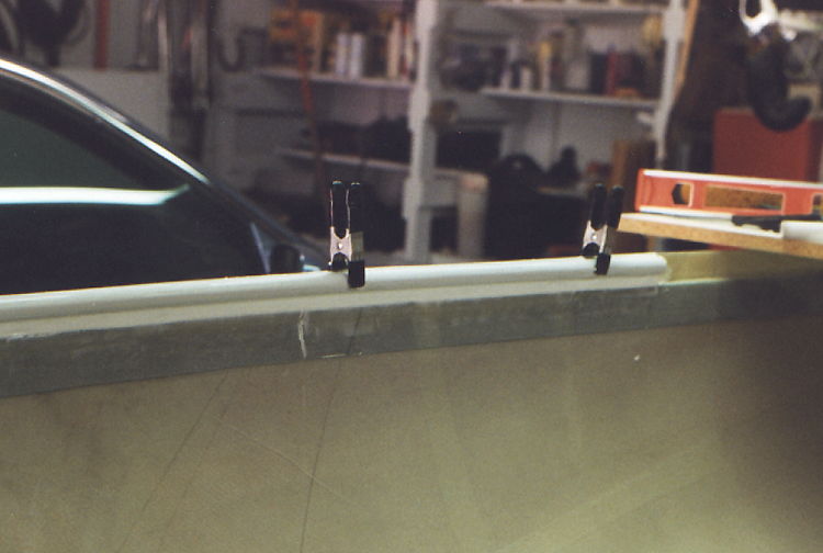 |
| Tacked into place with 1/4 inch plywood spacer used to position
conduit level with the 0.0 waterline. |
Micro mix used to fill the space between conduit and fuselage
side on top and smooth transition into longeron. |
Sand and layer a two ply bid over and around conduit finishes
and provides very strong edge. |
FRONT SEAT BACK
ASSEMBLY
To help facilitate the installation of the front seat back and the rear seat
back, the control console sides, (4 pieces), are cut following the outlines
on the prepreg panel.
The lower end of the back of the front seat is mounted roughly three inches
aft from the rear edge of the center main spar.
-
Cut a 3 inch wide strip of prepreg panel and bond it on to the aft edge of
the center main spar using the forward console sides as a guide to the correct
angle. See figure XXX.
-
Tie this 3" wide strip to the main spar center section with a 2 inch wide
2 ply pre wetted BID strip. Fillet slightly to make a smooth finish for the
bid. (This must be a strong joint).
The front seat back will be installed to the back edge of this strip, and
angled back to where the seat back joins the upper side rail at stations
55.
-
Cut the seat pack panel from the proper section of standard prepreg panel
and fit it into position.
It is recommended that this seat back have two cut out panels to permit a
section of the seat to move forward for loading back seat passengers. A
continuous panel would be lighter and more rigid, but access to the rear
seat would be limited.
-
Cut the panels away to the configuration shown in figure XXX, and fill the
raw edges of the honeycomb panel with a dry MICRO paste. Note how the side
edges are angled to allow the bid to move from one side of the panel to the
other side.
-
Use clear tape or plastic (acetate is best) to provide a "parting" surface
for the flanges which will be added to the moveable panels.
-
The flanges shall be a minimum of 4 plies thick with about 1/2 inch overlap
to prevent the seat panel from swinging back under seating load. Apply two
ply’s to one side, bringing them up onto the top, and then apply the
other two ply’s on the top side overlapping the bottom ply’s. See
figure XXX.
-
The top edge of the seats shall be stiffened with some carved foam, overlaid
with pre-wetted BID.
-
The center section shall be reinforced with a section of plywood with BID
on both surfaces (see figure XXX). Overlap the folding panels about 1" to
insure a positive stop under heavy loading.
-
Fasten the folding seat backs at the bottom with a strip of locally procured
hinge on each panel using #8-32 flat head screws.
-
Tack into place with dabs of 5 minute epoxy.
-
Bond the lower edge to the 3 inch wide angled section bonded to the center
main spar with two ply, 3 inch wide wetted BID on each side.
-
Bond the seat edges to the fuselage inner wall with 2 inch wide BID both
sides. Read the next instruction before doing this step.
-
The load bearing points of the top edge of the seat back shall be reinforced
with a gusset of plywood covered with at least 3 layers BID both sides, to
keep the backs supported under heavy seating loads. If the seat back has
been left at its factory height, the gussets should be installed after the
top fuselage section has been installed.
REAR SEAT BACK
INSTALLATION
-
Cut the rear seat, back panel from the prepreg following its respective outline,
and fit it into position (bottom at station 78 and top at station 86).
The center section of the rear seat back may be modified to provide easier
access to baggage etc. by cutting and hinging a section of the seat back.
Make one large folding piece with the bottom ending 1" above the elevator
hard point that is to be installed. Follow the same procedures as in the
front seat back fold downs fabrication. Allow at least 3 inches of material
at the fuse edges to maintain strength as this seat back is a structural
support. See figure XXX.
-
Add a hard point for the elevator idler bracket in the location shown in
figure XXX. Use 1/4 inch plywood, cutting away one surface of the panel and
inserting the wood section.
-
Close out with a four layer BID patch with at least a one inch overlap around
the perimeter of the hard point.
-
Install the seat back with the bottom edge at station 78 and the top edge
at station 86. "Tack" the seat back in place with 5-minute epoxy, and verify
the location while the epoxy cures.
-
Fillet all edges. Bond the seat back assembly in place with 3 inch wide 2
ply BID. (see figure XXX).
-
Insert a 1 1/2 inch square hard point on each side in front of and near the
bottom of the seat back on the outside fuselage skin, for the rear seat lap
belt attach points. See figure XXX.
-
Apply a 4 ply BID on the outside and inside of the fuse’ with at least
a 1 inch extra overlap over the seat belt hard point.
-
Cut a 3 inch wide strip of the same honeycomb panel as used for the seat
back, and install it to stiffen the upper edge of the seat back (see figure
XXX). Follow the same procedures as with the front seat back as to installing
support gussets and the fuse’ Top.
-
Fabricate a 1 inch wide angle of 4 ply BID to serve as the rear support for
the removable seat bottom panels. Use a piece of 2" angle aluminum, purchased
from the local hardware store, to use as a mold for the angle lam. (apply
a small amount of wax to the aluminum before appling glass and resin.)
-
Lay out a straight line from the seat forward support ( this is the stiffener
bonded onto the top of the landing gear box), over the rear spar, to the
bottom of the rear seat back, to establish the height for attachment of this
angle to the seat back. Bond the prefabricated angle into position onto the
seat back front surface.
CONTROL CONSOLE
- FRONT SEAT AREA
Many of the control functions are mounted to and/or routed through - the
center "console" . The console has the form of a "tunnel" that runs from
the front seat forward edge to the rear seat back and is boxed up between
the seat areas on each side. The panels should have been cut out of the prepreg
material in a preceding section.
-
Test fit the panel sections into the location shown and do any fine trimming
which may be required for a proper fit . The tunnel width will narrow from
a 4 inch outside width in the front seat area to a 3.5 outer width at the
rear seat back.
The rudder cables will be routed against the walls of this tunnel section
to minimize friction and avoid interference or conflict with any of the other
functions in the tunnel. To accomplish this, the cables will be run inside
hard nylon tubing attached to these walls.
-
In the front section, the nylon tubing should be held straight by inserting
1/8 in dia. rod into the tubing while the nylon tube is bonded in position
on the inner wall with an overlay of 2 ply pre-wetted BID tape (Extend roughly
3 inches of free end of this tube forward of the panel, through the seat
forward bulkhead).
In the rear seat tunnel area, a groove will be cut on the inner surface of
each side panel. The plastic tubing section will be bonded into the side
panels, to carry the rudder cables through this area with low friction and
protected from damage or jamming.
-
The locations of this channel will be marked on the second section console
sides. Verify that this line is continuous and straight, and will just clear
the upper surface of the center main spar cut out, and the cutout for the
main gear box. Also check that the line is directed in a straight line which
will project aft to the level of the rudder bell-crank.
-
Cut away a strip of the inner skin about 1/4 inch wide, and remove core material
along the cables path. Fit the supplied lengths of nylon tubing into these
grooves and bond in place with thick MICRO paste. Close out the open face
with a one inch strip of 2 ply BID.
Several "hard points" will be installed in each panel side. ?
In the forward section, there are two for mounting bolts for the flap lever
quadrant ( on the left side panel), and two more hard points for the inner
lap belt attach points for the front seat belts (one on each side panel).
-
Use segments of the 1/4 inch aircraft plywood for the core fillers. The hard
points for the flap brackets should be 1" square. See figure XXX for the
locations of these "hard points".
-
The hard points for the seat belts should be a minimum of 2" square. These
hard points are a critical item. These areas should be covered with 8 layers
of BID. Make sure that each layer has a minimum overlap on all three surfaces
of 2 inches. A tapered overlap will spread the load more evenly and present
a better appearance if neatly accomplished. The 2 inch overlap is MINIMUM
for any layer.
ELEVATOR IDLER BELL
CRANK
Fabricate from channel and mount to seat back
The desired routing of the elevator push-pull rod, and the rather extreme
length of this rod assembly suggests the value of a two piece push-pull rod
assembly, with an idler bell-crank located behind the rear seat assembly
. This idler assembly will stabilize the long push-pull rod, and allow the
path to be broken into two sections with a good stabilizing point near mid
span. This idler bell-crank also establishes the desired ratio of elevator
travel relative to stick travel. The bell crank slightly amplifies the travel
by setting the shorter leg of the idler on the forward side hooking into
the stick push rod. The longer, aft arm of the linkage hooks to the push
rod leading to the elevator control arm. The kit supplies high quality rod
ends for these joints to minimize friction and end play in the linkage .
-
Use figure X-9 as a guide, and fabricate the elevator idler bell crank from
a piece of the furnished aluminum "C" channel.
Figure -9, Elevator Idler Bell Crank.
-
Use the rod ends from the push rods to establish the number of washers to
provide a good fit in the channel sections as shown in figure X-9.
-
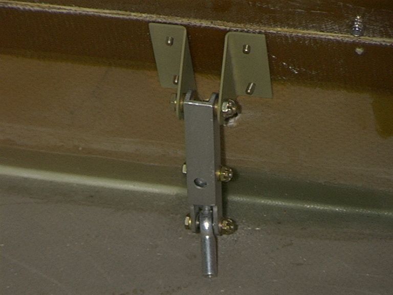
Insert the bushings in the pivot end of the idler lever, and use the assembly,
with the mounting angles (part KS-3 ) to aid in drilling the mounting holes
(4) for this assembly. Make sure the holes are aligned square to each other
and the bell crank to preclude any binding.
-
Countersink these holes from the forward surface of the rear seat back and
install the assembly using the 4 flat head #10 - 32 screws supplied (MS2469lS56).
(See figure XXX as guide for these operations.). Four countersunk washers
(A315-017-24A) are also supplied for the flat head bolts selected for the
idler mounting area to minimize "fretting erosion" of the composite
material.
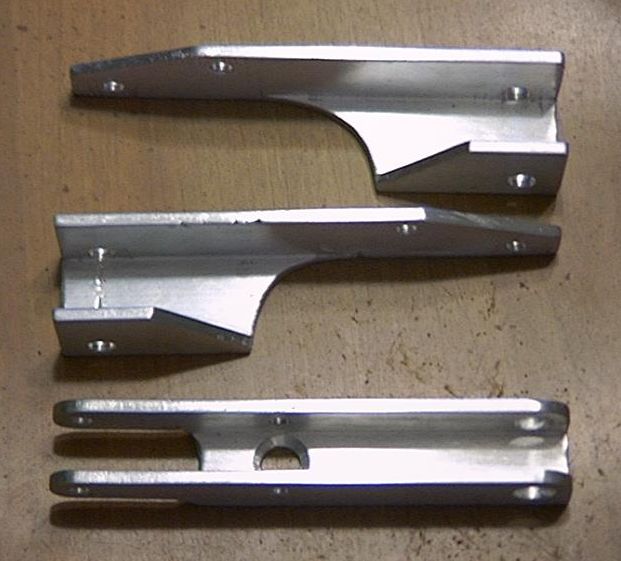 |
 |
Elevator Idler arm show on bottom.
Cut from aluminum "U" channel. |
Elevator Idler shown mounted on back of
rear seat. |
SEAT BOTTOM
ASSEMBLY
The seat bottom can be tailored to individual requirements, but the enclosed
instructions describe the method which has worked well on the factory airplane.
The seat panels should be fabricated from the 1/4 inch standard panel material
supplied, or any other similar core material desired.
FRONT SEAT
The front seat bottom panel position is established as a straight line between
the top edge of the panel which forms the front of the seat "box" (station
31 bulkhead), back to the top surface of the center main spar. The left and
right seat bottom panels will be separated by the control tunnel between
the two front seats.
-
Draw a line on the outer faces of the tunnel, and the fuselage inner walls,
and add seat support in the form of "glass" angles formed from about 3 layers
of prelam tape. (use angle aluminum as a mold for the support lams).
-
Make the seat bottom core section a little oversize, (read the next instruction)
and trim to fit.
-
Cut through one skin of the panel in two places. One place about 3 inches
forward of the aft line so this part of the seat can sit flat on the spar,
and again along the edge of the forward support panel so the seat can be
bent flat under the passenger knees.
-
Reinforce with one ply BID overall on each surface and an extra ply of BID
tape at the bends.
-
Cut a generous opening in the front edge of the seat to allow full control
stick travel, and dress the edges of the opening with flox.
-
Trim the edges of the panel to fit closely into place against the tunnel
sides in the center, and the curved fuselage sides on the outer edges, to
keep it from shifting position while in flight.
-
It is desirable to hinge these seat bottom panels at the rear edge to provide
access to the control mechanism, and to provide storage space beneath the
seat . Reference figure XXX to clarify any questions.
REAR SEATS
The rear seat bottom placement is also somewhat controlled by the height
of the panel installed for the seat front (on top of the gear "box"), and
the location of the "glass" angle mounted to the seat back. The location
of this seat bottom panel is rather non critical since there is a surplus
of head room in the rear seating positions. A higher seat bottom will provide
more storage space beneath the seat, and also provide better visibility over
the pilot and front seat passenger. The fabrication of this panel should
closely follow the procedure used for the front seat, With a higher seat
placement, a bench configuration could be used in the back seat as long as
adequate seat belt provisions are supplied, and total back seat loading does
not exceed 340 lbs.