Tri-R Technologies
TR-4
BUILDER'S
MANUAL
This Builder's Manual is NOT the official manual
as published by TRI-R Technologies.
FUSELAGE
Quick Links to Wing Assembly Sub-Sections:
SPAR
PREPARATION
LEVELING
AND FIXTURING
SPREADER
STICKS
TEMPORARY
FITTING OF THE FUSELAGE TOP
FIREWALL
FIREWALL
FRONT FACE
ADDED REINFORCING IN FIREWALL AREA
STATION
139.5 BULK HEAD
STATION
180.5 BULKHEAD
MAIN
SPAR AND OUTBOARD SPAR PRE ASSEMBLY
REAR
SPAR
MAIN SPAR LOCATION AND INSTALLATION
POSITIONING
SPAR
MOUNTING LAMINATIONS
MAIN
GEAR BOX REINFORCEMENT
SEAT
FRONT BULKHEAD & CONTROL MOUNT
FUSELAGE
BELTLINE
CONDUITS
FRONT SEAT BACK ASSEMBLY
REAR
SEAT BACK INSTALLATION
CONTROL
CONSOLE - FRONT SEAT AREA
ELEVATOR
IDLER BELL
CRANK
SEAT BOTTOM ASSEMBLY
FRONT
SEAT
REAR
SEATS
FRONT
FLOOR ASSEMBLY
STICK
LINKAGE ASSEMBLY
FLAP
HANDLE ASSEMBLY BRACKET
AILERON
IDLER INSTALLATION
FLAP ACTUATION TORQUE TUBE INSTALLATION
RUDDER
IDLER LEVER INSTALLATION
HORIZONTAL
STABILIZER
INSTALL
RUDDER POST
ELEVATOR AND PUSH/PULL ROD
INSTALLATION
RUDDER CABLE ROUTING AND
INSTALLATION
MAIN
GEAR INSTALLATION
BRAKE
LINE INSTALLATION
FIN
RIGHT HALF INSTALLATION
INSTALL
LEFT FIN HALF
HANGING
RUDDER
INSTALLATION
OF FUSELAGE TOP
BAGGAGE
AREA BACK PANEL
DOOR
PREPARATION
WINDOW
INSTALLATION
DOOR
LATCH ASSEMBLY
MOUNT
DOORS
LATCH
PLATE INSTALLATION
AIR
STRUT INSTALLATION
REAR
WINDOWS
INSTRUMENT
PANEL
WINDSHIELD
FIREWALL
-
The firewall will be fabricated from the 1/4 inch plywood piece included
in the kit parts. This piece of plywood should have the outline and location
of major features (such as engine mounting locations) marked on it by the
factory. Some slight amount of trimming will be required from the factory
line to the final fit, to the fuselage.
-
Some of the plywood may be warped from shipping so some degree of straightening
should be performed at this time. Storing on a flat level spot with weights
or clamping with some one by four material should flatten the material. In
severe cases temporarily attach some I by 4 strips on edge to the engine
side of the plywood to hold it flat.
-
The firewall cutout should be inserted into the forward portion of the two
fuselage halves and pushed back to the reference location. The back surface
of this plywood firewall is to be set at station 0.0, with considerable care
and precision, since this will be used as the reference for many of the assembly
procedures. Station 0.0 is described as the edge of the "joggle" for the
cowling rear overlap (see figure 4-4).
Figure-4: Firewall Position
 |
-
Four holes about 1/16 in. dia. may be drilled around the perimeter, through
the edge of this "joggle" to visually determine the correct location.
The plywood may be temporarily spaced with large pins or small nails through
these holes and may be temporarily secured with small nails or pins through
small holes drilled to the center of the plywood.
-
Assure that the firewall is vertical and square in place. Use the level line
on the firewall to assure proper vertical placement relative to the Waterline
references on the lower fuselage section (the joggle at WL -1.25 and the
trimmed edge at WL 0.0).
-
Verify the fit with the upper fuselage half before ''attaching'' the firewall
panel to the lower section with five minute epoxy ( or CA ). As mentioned
before, when "tacking" in place with five minute epoxy (or CA), be careful
not to spread the epoxy over a wide area. The fast curing epoxies have
significantly lower structural bond strength than that of the slow cure mixes,
and any area covered by the fast epoxy will have this "weak link" in the
joint. Keep the five minute epoxy "tacks" as small and local as practical,
.
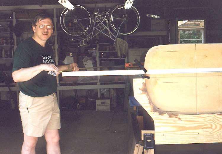
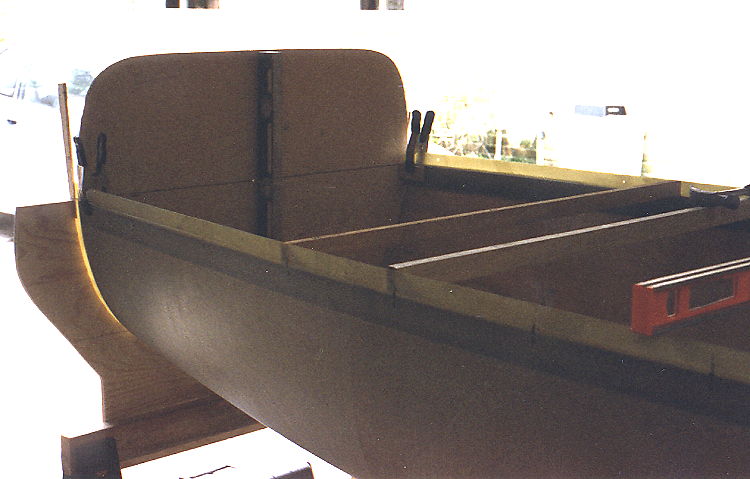
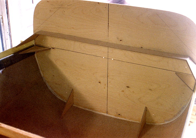
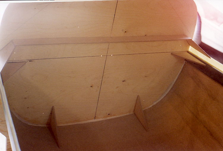
Figure 128-130: Filewall Positioning
 |
 |
 |
Measuring from the tail to square the firewall to the fuselage.
Extending
the measurement point increases the accuracy of the measurement. |
A level attached to the inside of the firewall helped in the
level process and
to remove a bow from the plywood. |
Horizontal line is at the waterline 0.0
and the vertical line is center line. The shims helped clamp sides
against
firewall during bonding. |
FIREWALL FRONT
FACE
-
Prepare the inner surface of the fuselage flange area and several inches
back from the zero station in preparation for the bonding operation. As always,
remove all peel ply and debris and clean and roughen these areas.
-
Also prepare the forward and aft face of the firewall for bonding. Roughen
the bonding areas with very course sand paper (50 or 80 grit)
-
Trim off the forward facing cowl flange of the bottom of the fuselage between
BL-8L and BL- 8R (a total of 16 inches wide) and radius the edge.
-
Prepare any of the remaining inner surface of the flanges and the local bottom
surface of the fuselage for bonding.
-
MICRO/FLOX fillet the joint in all areas. Make up enough 3 inch wide two
ply pre-lam BID tape to apply to the flange/firewall joint on each side around
the firewall to the fuselage bottom surface.
-
The engine mounting points will be marked on the plywood firewall panel.
It will be beneficial to drill small pilot holes through the firewall to
denote the location of the engine mount bolts.
-
Cut out the triangular shaped gussets and the firewall cross stiffening strip
from the same plywood panel that was used for the firewall. The patterns
for these parts should also be factory marked on this panel.
The full width stiffener should be tied into the edges of the upper gussets
(cut to length if necessary).
-
Attach these plywood gussets and the firewall cross stiffening strip on the
inner surface of the firewall panel and to the lower fuselage section inner
wall with dabs of five minute epoxy (CA). The location for these stiffeners
is shown in figure XXX.
Figure -5, Fire wall gussets and stiffener.
 |
-
The lower edge of these upper triangular gussets shall be aligned with the
top surface of the upper edge of the fuselage flange (waterline 0.0). These
gussets should be angled upward such that the lower surface of the plywood
is 1.5 inches from the center of the engine mount bolt hole. This will provide
adequate clearance for the washer which will be installed at each of these
mounting points. Ref. Figure 4-5
-
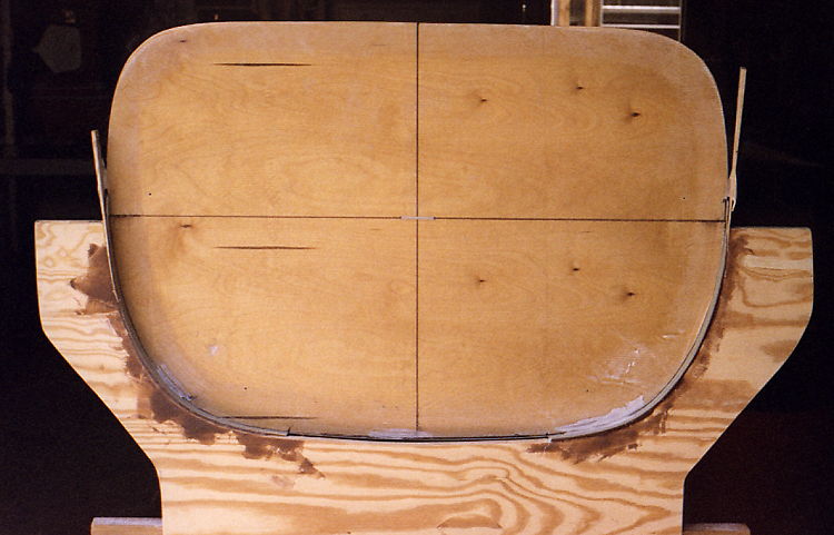
Firewall has been initially bonded into
place and bracing tacked in place.
|
Note horz and vert alignment lines. The
two holes are for a nylon strap to hold a tape
measure for one handed measurements. |
-
A fillet of dry FLOX should be worked into place on the underside of the
joint along the fuselage flange providing proper backing for the subsequent
layers of BID.
-
The lower gussets of this upper set will be mounted with a 1.5 inch clearance
to the mounting bolt holes and horizontally. Ref. figure 4-5
-
The gussets for the lower mounting holes shall be installed 1.5 inches on
the inboard side of the engine mount bolt center line location as marked
on the firewall pattern and shown in the figure 4-5.
-
Note all the areas that will be covered by the bonding layers of BID. Clean
and abrade these areas with coarse sandpaper and then wipe down with MEK
or Acetone .
-
Make paper patterns in roughly the shape and sizes shown in figure 4-6, 4-7
& 4-8.
Figure -6, Gusset pre lams.
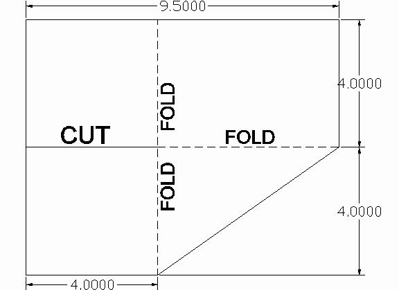 |
Figure-7: Gusset pre lams.
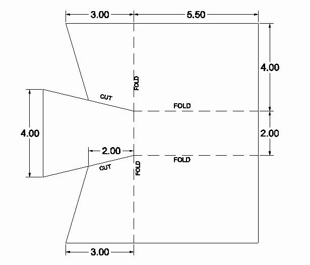 |
Figure-8: Between lower gusset pre lam.
 |
The areas between the upper braces will be the most demanding because of
the a angle between the gussets. Try to optimize the pattern to provide full
coverage of the firewall in the bolt area with the three layers of each overlap
( 24 layers total in these mounting bolt areas).
-
Make up two 4 layer BID sections of the required size before hand. NOTE:
make the first 4 layer section oversized in order to provide generous added
overlap on the firewall surfaces. Make up these reinforcements in two stages
with decreasing amounts of overlap of about 1 inch in each stage. This will
avoid dumping all the concentrated loads on one line. We recommend that you
use the suggested procedure for "pre-lams" in the following instructions.
The lower engine mount areas have only one plywood angle per hole. The area
between these gussets with a total of 8 plies of pre-lam. This is the large
pattern - 18 inches long. (this is the nose gear mounting area). The fire
wall area next to the gusset will have the corner overlapped for a total
of 16 plies.
The other side (bolt hole side) will also get an 8 layer set of plies, doubling
the overlap at the mounting bolt points for a total of 16 plies at this time,
(4 added plies will be installed during floor installation).
Before each new lay-up wet out the surface that the pre-lam BID will cover
with a thin coat of brushed on epoxy. This applies to all areas where the
pre-wetted BID is to be applied. This helps to assure a good bond in these
areas.
-
Prepare the first 4 ply pre-lam for a upper gusset set and apply to the firewall.
Remove one layer of plastic and install between each set of gussets with
the wet side to the structure. Fold the "ears" of this BID such that there
is the required number of overlaps bonded on the back side of the firewall
where the holes will be subsequently drilled for the mounts. Remove the plastic
backing as you install the glass cloth to avoid having any plastic in the
overlap areas. Work any bubbles out of the resin with a brush or squeegee.
DO NOT MAKE UP MORE THAN ONE 4 PLY PRE-LAM AT A TIME AS YOU MAY EXCEED
THE WORKING TIME OF THE RESIN AND WILL HAVE TROUBLE REMOVING AIR BUBBLES
AND GETTING THE PRE-LAM TO LIE FLAT.
-
Prepare the second 4 ply pre-lam for the same upper gusset set and apply
over the first pre-lam. Follow the same procedure as above and in all subsequent
operations.
-
Insure that all air bubbles are remove and the pre-lam fit is good.
-
Do the same as above to the second upper gusset set.
-
Prepare the first 4 ply pre-lam for the underside of an upper gusset set
and apply to the firewall.
-
Prepare the second 4 ply pre-lam for the same underside and apply.
-
Do the same as above to the second upper gusset set.
-
Prepare the first 4 ply pre-lam for the lower firewall center section (between
the two lower gussets), and apply.
-
Prepare the second 4 ply pre-lam and apply to the first.
-
An added 6 by 10 inch 4 ply prelam should be bonded between the two bottom
engine mount gussets with a 3 inch overlap on each the firewall and the fuselage
bottom surface as added strength for the lower gear mount.
-
Again, insure that all air has been removed and the prelam lays flat against
all surfaces, especially where the firewall to fuse fillet is.
-
Following the procedures above, make up each set of 4 ply ( two sets of four,
each side of gusset, for a total of 8 ply’s ) pre-lams and apply to
the fuselage at the lower outside (engine mounting hole side) of the lower
gussets.
Completing the upper surface of the upper gussets ( which will be laminated
into the upper fuselage half ) will require special treatment and will be
delayed until the fuselage top is being permanently installed. ( Except as
noted below )
Any previously cured BID layers which will be bonded to in later steps must
be roughened and cleaned prior to applying added layers. This applies to
any portion of the assembly process, and should be kept in mind when scheduling
lay-up work . What you leave unfinished in one work session will have to
be re prepared before continuing at the next work session.
ADDED
REINFORCING IN FIREWALL AREA
-
Bond the uncovered upper surface of the cross stiffening strip in place with
a 6 layer BID tape. Use roughly a three inch overlap on the plywood firewall,
and a piece long enough for a full overlap on the upper engine mount gussets,
(trim this prelam at the fuselage edge - this section will be bonded to the
fuselage after the top is installed)
-
Do the same thing with a 3 layer BID tape on the lower surface of the crosswise
stiffener but just use a 2 inch overlap.
This is the reinforcement for the upper nose gear attach point. The heavy
loads on this gear mounting area are the reason for the generous number of
layers. Green trim the surplus glass cloth overhanging the edge of the plywood
parts or grind these edges to shape after curing.
IMPORTANT - Any remaining unbonded perimeter of the firewall and the lower
fuselage section, should be taped with a two layer three inch wide BID tape.
Reference figure XXX showing engine mount reinforcements.