Tri-R Technologies
TR-4
BUILDER'S
MANUAL
This Builder's Manual is NOT the official manual
as published by TRI-R Technologies.
WING ASSEMBLY
Quick Links to Wing Assembly Sub-Sections:
SPAR
INSPECTION
MAIN SPAR AND OUTBOARD SPAR PRE ASSEMBLY
WING
ASSEMBLY JIG
UPPER
WING SKIN PREPARATION
REAR
SPAR PREPARATION
AFT
RIB INSTALLATION
MAIN
SPAR
SPAR
FILLER BLOCKS
TRIAL FIT
UP
FUEL
OUTLET
FUEL
MEASURING PROVISION
ANTI-SLOSH
VALVE
FUEL
VENT LINES.
HARD
POINT FOR THE AILERON BELL CRANK
BONDING
UPPER SKIN ASSEMBLY
PITOT
STATIC LINES - LEFT WING
SPAR
POCKET CLOSE-OUT
GAS
CAP
FUEL
PROOFING
AILERON
HOLE IN REAR SPAR
AILERON
HOLE IN MAIN SPAR
WIRING
CONDUIT
AILERON
BELL CRANK
PREPARATION
OF LOWER WING SKIN
FUEL DRAIN
COCK
INSPECTION
PANELS AND ACCESS COVERS.
AILERON
BELL CRANK INSPECTION PANEL
SUGGESTED
PITOT TUBE FABRICATION
OTHER
ACCESS COVERS
INSTALLATION
OF LOWER SKIN
STIFFEN
TRAILING EDGE
INSTALL
HINGES
INSTALLATION
OF WING TIPS
ACCESS
PANEL CONSTRUCTION
UPPER WING SKIN
PREPARATION
-
Select the proper wing skin for the wing panel you are planing to assemble
(the inboard section of the upper wing skin can be identified by the extra
ply of outer glass in the wing walk area, this can be identified in that
the trailing edge of the wing skin is more stiff at one end than at the other).
-
Peel off all the peel ply and any residual molding materials, particularly
in the areas where you will be bonding the spars and the ribs.
-
Trim the rear edge of the selected upper wing skin along the scribe line
provided on the outer surface, as follows: Darken the scribe line with the
side of a pencil lead. Cut along this line with a fine tooth hand saw or
a fine tooth jig saw.
-
The inboard edge of the skin will be buttline 22 after it is trimmed as follows:
Locate the joggle near the inboard end on the top skin - this is buttline
24 (see the fold out for clarification). Measure 2 inches inboard (towards
the edge) from the buttline 24 reference, and draw a straight line
along the edge of the skin, (this will become buttline 22). Now carefully
trim the edge of the skin to this line. Make these trim cuts carefully and
precise, since this cut edge will be an important measurement point for assembly.
-
Position the upper wing skin in the assembly fixture, centering the skin
for the same overlap at each end. Make sure the areas on the skin that are
to be tack glued are free of mold wax or these areas will ether not adhere
or will become unstuck later during assembly.
-
Pull the leading edge contour into place on the templates, and. "Tack" into
place with a few dabs of bondo, 5 minute micro/epoxy, hot glue or CA
(cyanoacrilate). (these materials will be very useful for the temporary fixturing
of parts during assembly. Any of the three are equally applicable, but in
any case avoid excessive amounts, and do not let them displace final bonding
materials in final assembly, since they are much weaker than the final adhesive
materials.)
REAR SPAR
PREPARATION
The wing rear spars are identical and interchangeable. Select a rear spar
for the wing section that you are building at this time.
-
Trim away any surplus edge material and remove all peel ply and other non
structural manufacturing materials. Sand the edges of the fiberglass parts
to make them safe for handling. Clean all mold wax etc. from the spar and
roughen the bonding flanges.
-
Locate the inner end of the selected rear spar, as follows: identify the
end of the spar where the core material for the web is made from a 4 inch
long section of phonetic, this can be accomplished by holding the spar up
to a bright light to identify the edges of this solid block, and at this
time, mark the center of the block as closely as possible. The center of
this block is to be located at buttline 22 where it will be drilled for the
rear spar bolt.
-
Measure 1.75 inches forward of the trailing edge in several places (or use
a square set at 1-3/4 in. as a guide), and draw a line the full length of
the skin. Lay the rear spar on edge, in place along the aft section of the
wing skin with the open face pointing forward, and locate the aft face
of the spar along the line.(see figure 7-8).
-
Align the center mark of the phonetic block to the inboard edge of the skin,
this aligns the rear spar BL-22 with the skins edge, which is also BL-22
. (See figure 7-8)
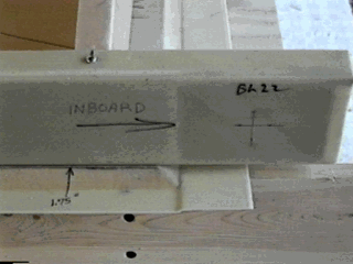
Figure -8, Rear spar installed. Note center of phenolic block.
-
Fixture the spar in place with several clecos or small screws.
AFT RIB
INSTALLATION
-
Mark the rear rib locations at their appropriate stations, as follows: 26.5,
50, 83, 116, and 153 inches respectively, (reference the fold out drawing).
Remember that the edge of the skin starts at buttline 22, so the first rib
will start at BL 26.5, (4.5 inches) outboard of the edge of the skin. Reference
figure 6-9,
Rib butt line dimensions are at the centerline of the rib foam core.
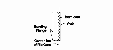
Figure -9, Rib Datum.
-
Clean the ribs flanges and face of all mold wax etc. and roughen the bonding
flanges.
-
Fit each rib into the inner/forward face of the rear spar at each rib location.
Sand the joggle in the upper and lower flange as required to get a very close
fit into the spar. In some instances, a lot of material may have to be removed,
but only enough to get a good fit. This fit is important as to the
stack-up of other wing components.
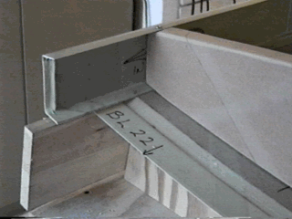
Figure -10, BL-22 along edge of skin, Phenolic Block shown at end of rear
spar. Rib to Spar fit.
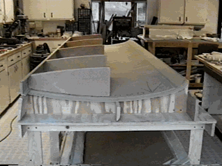
Figure -11, Aft ribs shown temporarily installed.
MAIN SPAR
-
Select the proper main outer spar for the wing side you have selected for
first assembly. Check the factory stamp if you did not mark the spar during
close-out.
-
Strip all peel ply etc., and prepare it in the same fashion as the rear spar
(clean).
-
Lay it in place on the upper skin, locate and mark all bonding surfaces including
the rib positions.
SPAR FILLER BLOCKS
In the outboard areas of the main spar where it is not boxed in by the spar
close-out, the installation of two filler blocks, to provide a surface for
bonding the aft rib sections, will be required. See figure 6-12. (one block
shown)
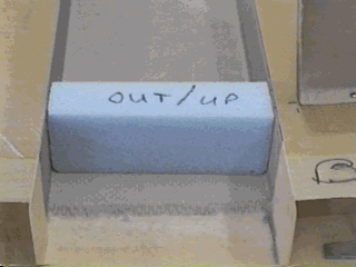
Figure -12, Foam filler block, note slip fit.
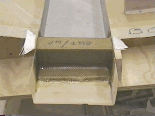
Figure -13, Two layers of BID. Cut BID overhang when green.
-
Make up blocks of blue foam 2 inches wide, to fill these areas, (note that
the spar flange thickness varies, so, individually fit these blocks into
their respective positions). Verify that the spar flange will not be distorted
as these blocks are bonded into place.
-
Keep these inserts flush with the edges of the spar flanges since this face
is critical in the overall assembly of the wing. Sand the face of the blocks
slightly below the surface of the spar flange edges to allow for the thickness
of the BID. (.025 in.)
-
Bond these blocks into the spar with a bit of micro slurry, and close out
the exposed foam surfaces with two ply’s of wet BID, with about 1 inch
overlap to the spar around the perimeter (do not overlap the top or bottom
surface of the spar since these surfaces are at their final dimension, and
any bulk in these areas will prevent proper fit up.
TRIAL FIT UP
-
Select six leading edge ribs for this assembly (there are no right and left
side ribs so just set out the required number of pieces). Again remove all
peel ply and sand edges for personal safety in handling.
-
Prepare the flanged bonding areas of the ribs in the same fashion as the
other bonding areas clean, roughen with sand paper and then clean again.
Also clean the web of these ribs, fittings and lay-ups will be bonded to
some of these ribs.
-
Set the main wing spar into position, with the spar close-out facing aft.
Align the spar BL-22 bolt hole with the inboard edge of the skin (BL-22).
-
Measure and mark the locations for the lead edge ribs as follows: 25.5, 50,
83, 116, 123 and 153 inches. The first inboard rib is at 25.5, one inch inboard
of the trailing edge rib. (3.5 inches from edge)
-
Number the ribs 1 through 6, just to keep things copisetic. On the web of
each rib, an arrow is molded into the web at the top edge, pointing to the
"top flange". If you cannot see it, run your fingers along the web by the
flange to feel it. Darken this arrow with a permanent marker or pencil. This
arrow points to the flange that is glued to the top skin. During assembly,
this arrow is down. The rib flanges will point away from the fuselage
in the right side wing, and toward the fuselage in the left side wing (photo
and sketches show a right side wing). If the rib does not fit the rib contour,
check the rib!
-
Clean and scuff the areas of the skin where you have marked for rib bonding
with 80 grit sandpaper.
-
The nose rib closest to the fuselage side (BL-25.5), must be cut short to
provide for the insertion of the center spar end during mounting the wings.
This cut should be made 3.5 inches forward of the spar forward face, and
parallel with the spar forward face. After cutting, cut out
1/8" of foam from the cut edge and fill with flox/micro.
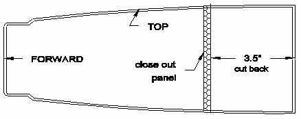
Figure -14, 3-1/2 inch cut back on rib #1 (BL-25.5). Close out panel
-
Screw or cleco the ribs onto the skin at their buttline locations.
-
The section of rib 25.5 that is left after cutting, is a portion of the fuel
tank system, so a panel needs to be cut from the supplied honeycomb "standard
panel", to close out this area, out to the next rib at BL-50. Fit this part
carefully since the joints will be potential fuel leaks. The aft face of
this panel is flush with the cut edge (fits inside the flanges) of the rib
and it will have constant height out to the next rib. Reference Figure
7-19.
-
The nose rib in the center of the fuel tank bay (at BL-83) should have it's
corners notched per the attached sketch to permit fuel to pass between sections
and avoid any bonding conflicts with the perimeter of the tank area. Reference
figure 6- 15,16 as to installation.
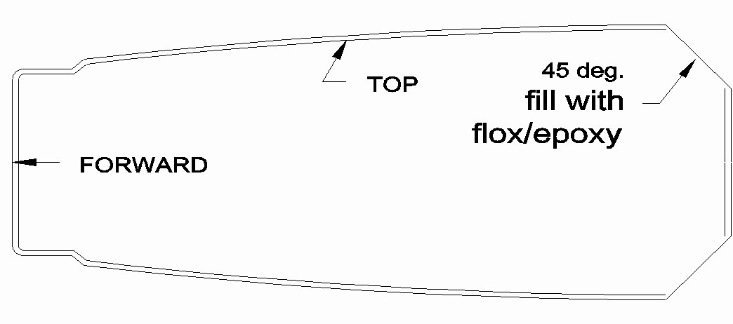
Figure -15, Rib #3, corners cut 45 deg.
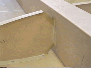
Figure -16, center tank rib in place.
-
Obtain, remove the peel ply, sand the edges, clean and then fit into position
the leading edge spar/fuel tank close out (C-25R, C-25L). The close out has
slightly more of an angle to one flange than the other. Determine which flange
has the greater angle by placing a square against the face of the close out
and against a flange. Mark this flange as the top. (this flange marked top
is assembled down).
Note that there is an extra nose rib added at BL-123 for carrying the mounting
point for the aileron bell crank, (reference figure 6-24), and that the rib
leading edge close out channel ends at the end of the tank bays at BL-116.
The open area forward of the leading edge ribs and the leading edge of the
wing, is for the aileron control rod coming out from the fuselage. The bell
crank will be mounted onto BL-123 rib in this short "bay" to transfer this
motion back to the aileron in a later step.
While the assembly is in the trial stage this would be a good time to review
mounting of vent lines, fuel level sensors, and the anti slosh valve. Drilling
holes and other preparations are best done on local components which have
been identified, and keyed into the selected location. It will be easiest
to install this plumbing into the loose ribs before bonding into place. Numbering
your ribs as mentioned earlier is a good idea.
FUEL OUTLET
The fuel outlet uses a finger strainer located at the lower aft corner of
the first rib (BL-25.5).
-
Use a piece of 1/4 inch by 1.5 by 1.5 inch aluminum (supplied), drilled and
tapped for the finger strainer.(3/8-24 pipe tap).
-
Reference figure 6-17 as to the location and procedure for installing the
fuel outlet.
-
If an injected engine is to be used, verify whether a fuel return line should
be provided for. If this is the case, this rib is also the appropriate location
for this line. If you are not sure of the engine to be used, install a return
port, it can be plugged if not used.
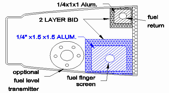
Figure -17, Fuel pickup, Fuel return and Fuel measuring layout guide.
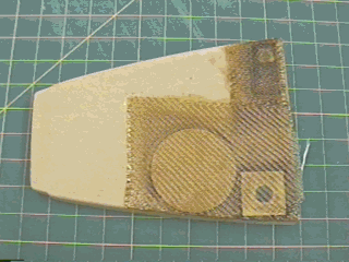
Figure -18, Note fuel level transmitter hard point.
FUEL MEASURING
PROVISION
This same first rib is the logical place for installation of a fuel level
sensing device. Reference figure 7-17,18. No fuel level measuring system
is provided in the kit. The tubular capacitive sensors are one of the most
popular devices. For this type, and/or many other fuel level sensors, the
most logical installation is through a prepared hard point in the web of
this inner rib for the mounting flange.
-
Locate the path for the length of this sensor element, and mark any next
rib sections where they must be penetrated, remove and modify these ribs.
-
Any hole through the rib core which will be exposed to liquid fuel shall
have the core cut out or forced down in the raw edge, and filled with a MICRO/FOX
paste.
-
Carefully follow the sensor manufacture's instructions for any bending that
might be required to implement the desired level measurements.
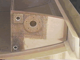
Figure -19, Fuel finger, fuel return and fuel level sender provisions.
Builders Note: Remember that the fuel finger
should be positioned as low and close to the corner as possible to pickup
the maximum amount of fuel. (The low point will be at the top during assembly.)
All fuel below the fuel finger will be unusable. (Bob
Reed)
ANTI-SLOSH VALVE
The anti slosh valve system is installed in the lower section of the second,
(BL-50) rib. This rudimentary check valve will keep this inner "header" tank
relatively full during agitation due to rough weather or enthusiastic
maneuvering.
-
This valve is a flapper configuration which is built in place, using a 3
inch length of hinge section and a 3 inch section of 1 X 1 X 1/8 inch aluminum
angle (supplied). Install the aluminum angle onto the hinge section (supplied)
with 2 or more rivets (figure 7-20).
-
Position the flapper valve assembly along the lowest point on this rib, near
the rear joint to the spar pocket close-out (Reference figure 7-20 and 7-21).
Make sure that there is sufficient clearance for the flapper to open and
close.
-
Mark the overlapped area covered by the flapper in the closed position, and
mark the mounting holes in the top part of the hinge assembly.
-
On the rib where the flapper valve will be mounted on the side with no flange,
a local strip of pre cured 2 ply may be added as a flange to keep the final
assembly bonding material from jamming the flapper. Do not epoxy this flange
to the bottom of the rib. This will cause the rib to sit high, and may cause
bonding problems with the bottom skin.
-
Make sure that the valve is clear to swing when mounted at that location.
-
Drill and cut out an opening for the fuel to flow through, that is well within
the flapper area.
-
Crush the core material around this new opening and "butter" on a protective
layer of FLOX/EPOXY around the edges.
-
Clean up the edges and the surface after the flox has cured.
-
Install the flapper valve. Again, check for freedom of movement (make sure
the flapper valve will move to the full up position without jamming against
the close-out panel). Check the coverage of the opening, and total flat seating
of the flapper surface.
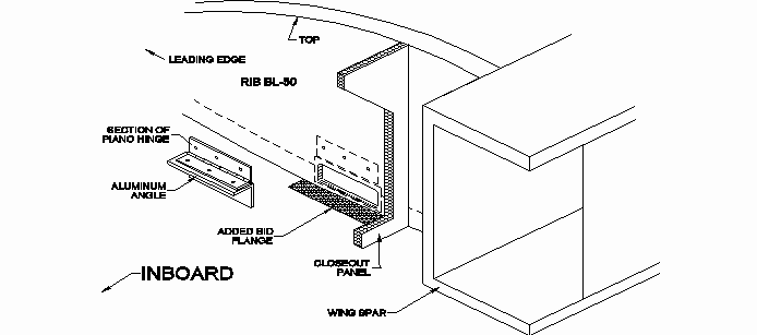
Figure -20
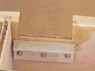
Figure -21, Fuel flapper valve. Note location in relation to close-out panel
at left of picture. No BID has been added to the flange as yet.
FUEL VENT LINES.
The fuel tanks must be vented to permit the entrance of,
or exit of, air equivalent to the fuel flow
-
The upper rear corner of the outermost rib (BL-116) of the tank bays, is
the preferred location of this vent. The lines are 1/4 inch aluminum tubing
furnished with the kit. Route this vent line out to the tip of the wing and
out what will become the lower surface as shown in figure 6-27. Fit this
line in place while the wing structural components are temporarily mounted
in place, drill the holes required for this line prior to bonding. Reference
figure 7-22 & 27. Note acetate (cellophane plastic) over BID lay-up,
this imparts a glassy finish to the BID lay-up after curing.
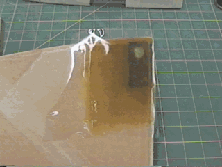
Figure -22, Fuel tank vent nipple fitting.
HARD
POINT FOR THE AILERON BELL CRANK
The front rib (BL-123) just beyond the last lead edge rib of the fuel tank,
is where the aileron bell crank will be mounted. The "hard point" for mounting
this bell crank can be installed most easily prior to the assembly process.
Reference Figure 7-22
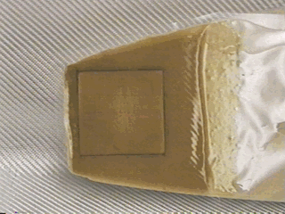
Figure -23, Bell crank hard point.
-
Make up a pre-assembly of the bell crank with its bearing, riveting the bearing
in place with a minimum of 4, AN 470 AD 4-7 rivets.
-
Make an assembly of the bell crank (KS-2), and the two mounting angle brackets
(KS-3), and a control rod end, using the appropriate bolt, nut and washers.
(AN4-13, An310-4, AN960-416)
-
Cut a piece of 1/4 in. plywood, about 2-3/4 by 2-3/4 inches. (figure 7-23).
-
Position this piece of plywood and the bell crank assembly on the rib
approximately 3/8 inch back from the leading edge and 1/4 inch below center,
towards the bottom skin. The aileron actuating rod end extending outward
from the fuselage, should be centered in the leading edge open area when
mounted to the top surface of the bell crank, adjust the vertical position
if not centered. (note again that we are building the wing upside down).
-
Mark the outline of the wood insert piece on the inboard surface of the rib,
Cut away the skin within this outline and remove the core in this area.
-
Clean the remaining outer skin, and insert the wood with FLOX/EPOXY adhesive,
and close out the hole with 2 plies of pre wetted BID.
-
Fabricate a 1/4 inch plywood spacer as shown, that fits the mounting area
of the KS-3 brackets.
-
Drill the 4 holes for the AN3-7A bolts through the plywood and the rib hard
point.
-
Mount the 4, 1OOO-3 nut plates using the bolts to fixture them. Install the
nut plates to the back of the hard point (outboard side of rib) by drilling
and installing 2 rivets (AN426AD-3-8) in each.
-
Cut clearance areas in the plywood, and the leading edge of the rib to permit
at least 30 degrees of movement in each direction, reference figure 7-24,
(on the left wing assembly the entire local section of the front flange must
be removed to permit free travel).
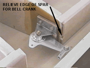
Figure -24, Bell crank installed to insure correct movement and fit. Note
slight cutout of backing plate and foreword rib edge to insure ample movement.
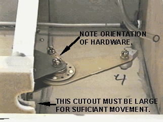
Figure -25, Left wing bell crank and cutout in rib. Note that the hardware
is mounted in the correct positions in this picture.
NOTE: Look at the options at the end of this section to see if you want to
install any options other than provided in the kit before bonding the bottom
skin to the assembly. Preparing ribs etc. now is easier.
BONDING UPPER SKIN
ASSEMBLY
-
Replace all the rib sections and spars following the modifications and assure
that none of the previous operations created any problems with the
fit up. When you are satisfied with the positioning, the bonding can be
initiated. This is accomplished working from the rear spar forward.
-
Remember to assure that the bonding surfaces are clean and clear of
all debris or greases and oils which might interfere with the bonding process.
-
Mix the Hysol adhesive per the directions and apply a bead along each joint
sufficient that there will be visible squeeze out on the edges of the bonding
areas (A small amount of FLOX may be added to the adhesive to thicken it
and assure that it does not flow out of the joint area).
-
Secure and lightly clamp all bonding surfaces with weights, clecos, or clamps
until the adhesive has sufficient strength.
-
Verify before the curing has started, that the fixture has not shifted, and
the assembly is still straight with no twists. Now leave the assembly alone
for at least two days for the Hysol to obtain sufficient strength before
continuing work.
PITOT STATIC
LINES - LEFT WING
On the left wing assembly, two vinyl or aluminum lines shall be installed
running just behind the main spar for the pitot and static air pressure for
the flight instruments. (The static opening may be installed on the fuse
if so desired, [both sides], make sure you know how these systems work before
modifying from the factory directions.)
-
Make an expansion loop in these lines, and route them forward to the location
of the aileron bell crank area. (expansion loops are absolutely necessary
in aluminum lines)
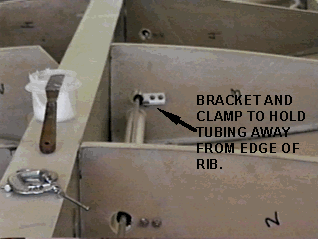
Figure -26, Pitot tube (vinyl). Note brackets and clamps.
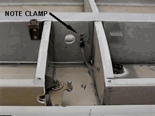
Figure -27, Pitot tube end.
-
Secure these lines so that there is no possibility of interference with the
aileron push pull tube sharing this space. Cut the rib holes much larger
than the tubing and use clamps and brackets to hold in place so that there
is absolutely no possibility of the tubing touching the ribs at any time
during fight.
-
Terminate the aluminum tubing in the region of the bell crank bay such that
the removable cover can serve both purposes of access to the bell crank and
the pitot static connections.
SPAR POCKET
CLOSE-OUT
With the ribs and spars bonded to the upper skin, this is a good time for
the installation of the honeycomb panel that was cut for the spar pocket
forward close out.
-
Fit this panel carefully since all of these joints must be fuel tight. Position
the panel with it's aft surface flush with the cut edge of the first rib,
and in a straight line to the face of the next nose rib.
-
With all surfaces previously prepared and clean, bond this panel in place
using 2 ply’s of 2 inch wide wetted BID strips on both sides, on all
three perimeters.
-
After these joints are cured, prepare a straight flat board to span the open
top face of this panel
-
With clear tape or other parting preparation on the face, clamp this board
in place as shown in the figure 6-25.
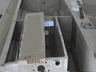
Figure -28, Flange lay-up board in place.
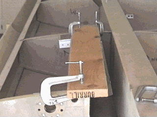
Figure -29, Rib flange bonded into place.
-
Laminate a flange on both the fore and aft edge of this panel using 2 ply’s
of 2 inch wide wetted BID strips.
-
When these flanges are sufficiently cured, remove the board, and roughen
and clean the surfaces of these flanges in preparation for bonding the bottom
skin.
GAS CAP
The gas cap neck will be installed in what will become the high comer of
the wing tank area. (On the top skin) Reference figure 6-26
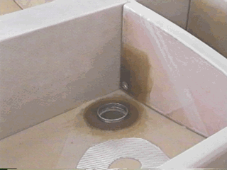
Figure -30: Gas cap filler neck installation. (left wing)
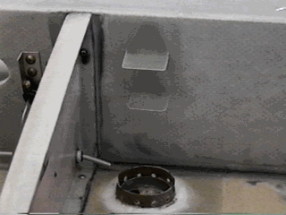
Figure -31, Neck, tabs and vent line installed. (right wing) Both tanks have
the same tabs, neck and vent lines installed.
-
Locate the desired position and hold the filler neck against the inner skin
and draw around the perimeter.
-
With a small electric grinder or similar tool, cut away this inner skin to
the edge of the marking, and clean away the core material without damaging
any of the outer skin.
-
Rough up the area of the skin around this cut out, and the metal surfaces
of the fuel filler neck in the bonding areas, and clean any debris from the
area.
-
Smear a FLOX mix around in the cut out area, working it into the core material
and then seat the filler neck in place.
-
Cut a three layer "washer" of wet BID and lay it around the filler neck.
Work this BID down into all the joint areas and work all the bubbles out
of the lay up.
FUEL PROOFING
Now is a good time to seal all of the pin holes and any other defects in
the surface and joints which will be exposed to fuel.
-
Lightly sand all the areas which will be wet with fuel and clean away any
oils, grease, fingerprints or loose debris.
-
Resin the entire area using a squeegee. Press firmly, and leave an almost
dry surface, paying particular attention to corners, and any areas where
the cloth weave is evident. Also resin both sides of any ribs inside the
tank area.
-
In about four hours, when the surface has partially cured, repeat the operation,
leaving the surface a bit wet this time.
This same operation will have to be repeated on the fuel tank areas of the
lower skin before it is assembled to the wing.
AILERON HOLE IN REAR
SPAR
Note the location of the aileron bell crank, and resulting routing of the
actuation rod.
-
Cut a roughly circular hole (about 1.5 inches dia.) in the rear spar to allow
passage of the actuation rod (reference the wing and aileron drawings and
parts for the correct location). Reference figure XX
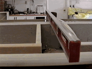
Figure -32, Using a straight edge to align holes.
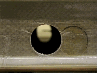
Figure -33: Aileron push rod hole in rear spar. Note Main spar hole in
background.
AILERON HOLE IN MAIN
SPAR
Note the location of the aileron bell crank, and resulting routing of the
actuation rod.
-
Cut a roughly circular hole (about 1.5 inches dia.) in the rear spar to allow
passage of the actuation rod (reference the wing and aileron drawings and
parts for the correct location). Reference figure 6-34
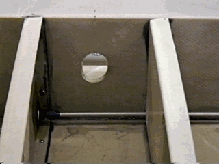
Figure -34: Push tube hole in main spar.
WIRING CONDUIT
Even if you are planing a "day VFR only" aircraft, it is a good idea to make
provisions for wiring to go out to the wing tip. The easiest way to ensure
protected access for later wiring is to purchase three ten foot lengths of
thin wall PVC pipe.
-
Install a conduit through the inner aft ribs, all the way out and through
the aft outer rib. Placement of this conduit is entirely optional, just assure
that there is no interference with flight controls. A good location is 2
inches up and 2 inches over, measured from the top skin up and the main spar
aft. Reference figure 6-35,36.
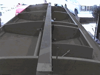
Figure -35, Conduit mounted in wing.
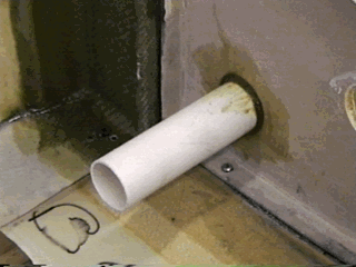
Figure -36: End of 1" thin wall PVC conduit for electrical wiring.
Builders Note: Remember when installing
the PVC for the electrical wiring that it will run the full length of the
wing and must be positioned so that it will not interfere with access to
the spar mounting bolt or with the aileron control rod. The best location
would probably be in the upper corner near the inside of the spar. This
should keep it clear of all other controls. Bonding the PVC pipe into
place might not be the best method, since some flexing of the wing over time
could break the bonds and cause a wearing away of the PVC. An alternate
method, which would allow for flexing, would be to use a good silicone to
bond the PVC into place. The silicone will allow the wing to flex and
will flex allowing the PVC to move slightly as needed. (Bob
Reed)
AILERON BELL CRANK
-
Install the aileron bell crank at the prepared location using the spacer
and the supplied AN3-10a bolts.
PREPARATION
OF LOWER WING SKIN
FUEL DRAIN COCK
It will be required to install a fuel drain cock in the lowest section of
the wing tank, to drain fuel and check for water accumulation.
Stay well out of any of the bonding areas for the ribs, spars, and internal
bulkheads. The overlapping tape from this insert could lead to a fuel leak
if it intrudes into a flange bonding area. Reference figure XX
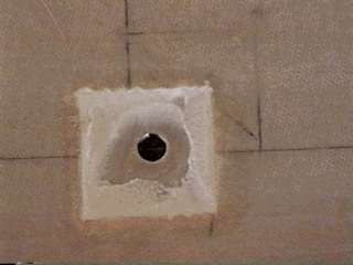
Figure -37, Fuel drain aluminum insert.
-
Locate the spot for mounting this drain as far inboard as practical, close
to the rib and as far aft as the flange on the spar pocket close-out panel
will allow.
-
Cut a 1.5 inch square from 1/4 inch thick aluminum (supplied), and lay on
the inner panel skin in the selected position, and mark around it.
-
Drill and Tap a hole centered in this pad - use a 21/64 drill and 1/4 in.
pipe thread tap.
-
Fill, or locally tape over this tapped hole to keep it from being filled
with resin in fabrication.
-
Cut away the inner skin and clean away core material to the inner surface
of the outer skin.
-
Bond the aluminum patch in this hole with thick MICRO/FLOX.
-
Cover with a 2 ply BID patch at least a half inch larger on all sides to
overlap onto the skin. Make sure this patch is well wetted out with no pores
or pin holes.
INSPECTION
PANELS AND ACCESS COVERS.
The aileron bell crank inspection panel and spar attach bolt access panel
(and any other panels that may be necessary, see figure 6-33) are probably
best installed at this point before bonding the wing skin in place. This
will give you a bit more access to both sides of the skin as you work on
the access panels, and will allow some added visibility inside the wing during
the bonding process. The suggested construction procedures for the access
panels are at the end of this chapter.
AILERON
BELL CRANK INSPECTION PANEL
The access cover will be 5 inches square, and located under the aileron bell
crank to provide access to both rod ends and the pivot bolts.
-
Mark out the outline of the door and cut carefully with a fine tooth, thin
kerf blade.
-
The cut edges of both panel and hole can be "hardened" for greater durability,
by cleaning back some of the core material at the edges, and filling with
a thick FLOX paste.
-
After removing and preparing the panel, coat the entire inner surface with
clear plastic tape., and place it back in the hole. Tape the cover back in
place on the outer surface, keeping the edges flush.
-
Now build up a flange on the inner surface using 3 layers of wet BID. Provide
extra surface under the comers of the panel, as this is where the anchor
nuts will be located for securing the panel, Reference figure 6-30 &
31.
-
Drill the holes through the cover and the newly made inner flanges, and prepare
these locations for bolts.
-
Cut out extra area around the holes in the cover; and fill these areas with
MICRO/FLOX, and countersink for the bolts after curing.
-
Install nut plates at the holes in the flanges for ready removal and replacement
of the panel.
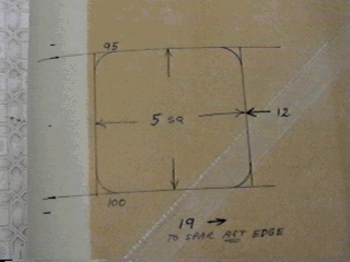
Figure -38: Bell crank inspection panel.
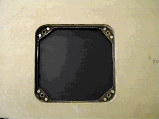
Figure -39: Flange and nut plates.
SUGGESTED
PITOT TUBE FABRICATION
The figure below shows a low cost effective way to construct your own pitot
tube assembly. If you intend to set up your aircraft for full IFR we would
suggest a commercial unit. See figure XX
OTHER ACCESS
COVERS
The basic wing plan form drawing enclosed in this section shows where
other access panels will be required. The wing assembly/disassembly procedure
will require a panel to be located aft of the outer main spar bolt at BL-46.
See figures 6-32.
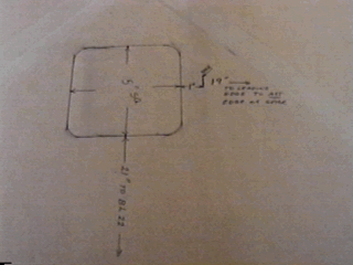
Figure -40: Spar attach bolt access panel.
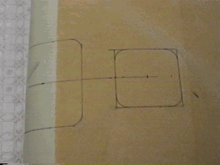
Figure -41: Landing light lens opening and access panel.
INSTALLATION OF
LOWER SKIN
Before starting the bonding procedure make sure that all fittings, electrical
conduit, electrical wiring, tubing’s and pipes have been installed and
inspected to insure that they are correct. It would be a good idea to leave
the bonding process until the next weekend so that you can look at the wing
panel assembly each night. This will insure that you have not overlooked
something. A good idea (if your ego can handle it) is to have your wife or
another pilot etc. look the wing over, allowing them to question everything
and anything. This will help prevent an error. It is better to do this now
instead of cutting your wing open later or worse yet, purchasing a new wing
panel assembly.
The lower skin must be carefully prepared for this final bonding operation,
since many of these bond areas are potential fuel leaks. Rapid and complete
assembly of this skin will be facilitated by having numerous tooling holes
and Clecos or small screws placed along the leading edge joggle. This will
assure rapid and accurate placement of the skin after placing the adhesives
required for bonding.
-
Mark out the area of the fuel tank system, all the way to the extremities
of all flanges. Measure and mark all rib and spar locations on the inside
of the bottom skin.
-
Wet the fuel tank areas with epoxy as outlined for the upper skin, to seal
all pores and any small leaks in previously installed flanges. As before,
squeegee out most of the resin for the first layer, follow this after partial
curing of the first layer with a wet layer for final sealing.
-
Double check all flange surfaces especially in joint areas where the fit
and resultant bonding may be discontinuous.
-
Repair any suspect surfaces building them up with a dry MICRO/FLOX mix and
"dressing" them for best-fit after curing.
-
Roughen all bonding areas, and clean them well.
-
Have an assistant help to practice placing the skin without sliding.
-
Dry test the fit both by visual inspection, and by thumping along the bond
lines to assure good contact.
-
Triple check all those surfaces that may be a potential fuel leakage, and
repair all fit up problems noted.
-
Round up a good supply of sand bags or other suitable weights for clamping.
50 pound bags of white play sand can be purchased at Home Base or other building
supply stores. Purchase six to eight bags. Tape the ends of the bags so that
the sand will not spill out.
-
Mix a thickened Hysol adhesive and lay a bead along all joining surfaces.
Have two or more people apply the Hysol, as this process can take some time.
This will also allow you to mix smaller amounts more frequently so there
will be less or no left over Hysol mix. (This is highly suggested in warm/hot
climates on hot days)
-
Carefully lower the skin into place, avoiding any wiping motion which would
smear adhesive.
-
Place weights along all bond lines, and watch for any surplus adhesive which
might plug fuel outlets or vents. ¾ in. screws can be used to secure
the aft ribs and aft spar to the skin.
-
Carefully observe the leading edge lap joint for gaps, use screws or clecos
to close any gaps (it will be a lot easier filling a bunch of holes, than
to correct any wavy joint after bonding is completed).
STIFFEN TRAILING
EDGE
The trailing edge of the wing skins should now be stiffened, and reinforced
for flap and aileron mounting.
Sight down the edges to see if any waviness can be seen. If any significant
distortion is noted, clamp that edge to something straight and rigid. Do
the upper and lower edges separately to facilitate this straightening.
Apply a 2 layer pre wetted BID tape along the entire length of the edge over
lapping the rear spar by one inch, and 3 extra layers in the areas where
hinges will be installed (3 places on the lower skin for flaps, 2 places
on the upper skin for aileron hinges). Note the angle aluminum clamped over
the 3 ply bid lamination. This makes a smooth FLAT surface for the hinges
to sit on. Do not clamp tightly, just enough pressure to smooth out the bid.
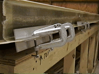
Figure -42: Two ply LAM & 3 ply hinge lamb.
Trim the hinge laminations flush to the trailing edges.
INSTALL HINGES
When the flap and aileron have been completed, the hinges should be fitted
and the nut plates installed, for installing and removing flaps and ailerons
to and from their respective wing locations.
-
Measure and mark the locations on the upper and lower surfaces of the wing
for the aileron and flap hinges. Reference the wing plan form drawings for
the hinge locations. (each hinge is 8 (eight) inches long.)
-
Cut and prepare five hinges 8 inches long. Make sure you peen or use cotter
pins in each end to retain the hinge pins.
-
Recess the hinge area on the trailing edge by 1/16 inch to allow for free
hinge travel. Before drilling any mounting holes make sure that the hinge
can rotate up more than 45 degrees. This will insure sufficient control surface
movement.
-
Carefully fit and align the respective control surface, cleaning up the mounting
surface for a secure flat mounting.
-
Cut and pre drill the hinges, (reference drill jig in elevator section and
use as a guide to drill the hinges).
-
Mark the holes in the wing trailing edge section, and carefully drill the
mounting holes (use the hinges as a drilling guide).
These surfaces have sufficient access such that fiber lock nuts can be used
for this installation. Nut plates may speed later maintenance operations,
but are left to the discretion of the builder.
INSTALLATION OF WING
TIPS
The installation of the wing tips can be delayed until closer to the final
assembly process, for storage and handling reasons, but this is the most
logical place to place these instructions. The wing tips may be made removable
by attaching them with roughly 16, 8 - 32 countersunk screws and appropriate
captive nuts and Tinnerman washers, but this hardware is not included in
the kit.
The recommended procedure is to fit up the tips, and close out the trailing
edge opening, then bond them permanently in place.
-
Fit up the tips by slipping them onto the recessed area at the outer edge
of the wing skins.
-
Some distortion or shrinkage may be present in the polyester glass tip moldings.
First attempt to get out any of this by clamping them in place as best as
possible and allowing the parts to set in this restrained condition for a
day or two if possible. The parts may be temporarily joined and clamped using
clecos or sheet metal screws - the holes can be easily filled in the finishing
process. If this does not cure the problem a few judicious saw cuts can be
used to flatten stubborn wrinkles, and a trailing edge cut can aid in stubborn
twists.
-
With the wing tip in this temporary attached position you will note that
there is an opening into the tip interior outboard of the aileron. Make a
trailing rib section to fill this opening from 1/4 inch foam.
-
Tack this in place with temporary adhesive and chamfer back the edge
of the foam through most of it's thickness.
-
Fill this chamfer with FLOX and close out the surface with 2 ply wet
BID.
-
Knife trim to the tip molding edge and flush in the surface neatly.
This will close out the opening and add significant stiffness to the tip
(be sure you did your fit up first).
-
Remove the temporary fasteners, roughen and clean the overlap bonding area.
-
Mix some thick MICRO/FLOX, coat both surfaces and re install the wing tip.
-
Again use the clecos or screws to hold in position and clamp the joint.


