Tri-R Technologies
TR-4
BUILDER'S
MANUAL
This Builder's Manual is NOT the official manual
as published by TRI-R Technologies.
WING ASSEMBLY
Quick Links to Wing Assembly Sub-Sections:
SPAR
INSPECTION
MAIN SPAR AND OUTBOARD SPAR PRE ASSEMBLY
WING
ASSEMBLY JIG
UPPER
WING SKIN PREPARATION
REAR
SPAR PREPARATION
AFT
RIB INSTALLATION
MAIN
SPAR
SPAR
FILLER BLOCKS
TRIAL FIT
UP
FUEL
OUTLET
FUEL
MEASURING PROVISION
ANTI-SLOSH
VALVE
FUEL
VENT LINES.
HARD
POINT FOR THE AILERON BELL CRANK
BONDING
UPPER SKIN ASSEMBLY
PITOT
STATIC LINES - LEFT WING
SPAR
POCKET CLOSE-OUT
GAS
CAP
FUEL
PROOFING
AILERON
HOLE IN REAR SPAR
AILERON
HOLE IN MAIN SPAR
WIRING
CONDUIT
AILERON
BELL CRANK
PREPARATION
OF LOWER WING SKIN
FUEL DRAIN
COCK
INSPECTION
PANELS AND ACCESS COVERS.
AILERON
BELL CRANK INSPECTION PANEL
SUGGESTED
PITOT TUBE FABRICATION
OTHER
ACCESS COVERS
INSTALLATION
OF LOWER SKIN
STIFFEN
TRAILING EDGE
INSTALL
HINGES
INSTALLATION
OF WING TIPS
ACCESS
PANEL CONSTRUCTION
SPAR INSPECTION
To assist you in making sure that your spars are correct we will provide
you with some dimensions that you should check to verify that you have properly
constructed spars. It is highly recommended that these checks be made prior
to any spar assembly. Your life could depend on it. These dimensions
are minimum and it is acceptable and expected for these measured areas to
be thicker than listed below.
Your measure
Center main spar: top cap measured at BL-O .720 in. ________
Bottom cap measurement at BL-O. 530 in. ________
Identify and verify the left and the right outboard main spars (wing spars).
The upper spar cap is noticeably thicker in the outer portion of the span.
The attach point (hard point) holes are pre drilled at the inboard end of
the spar.
Your measure
Outboard main: top cap measurement at BL-46 .320 in ________
bottom cap measurement at BL-46 .330 in. ________
There are many reasons for the caps to vary in thickness (manufacturing
techniques, overlaps of the materials during construction, and varying material
thickness from the manufacture.) This can add several thousands to the thickness.
Measure the thickness with a caliper or micrometer, about one half inch in
from the open edge.
Hard points: The hard points are located at BL-22 and BL-46
and are pre-drilled with a one inch hole. Verify that these holes are in
the correct buttline location in relation to the zero buttline, (centerline)
of the center main spar, and the inboard scribe line (BL-22) on the outboard
spar. Note that these holes are angled slightly off the spar longitudinal
centerline to hold the proper dihedral. (reference the fold out drawings
for buttline locations)
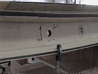
Figure -1, Bottom cap measurement at BL-46
-
The wing spar bolt hole locations, at butt lines 46 left and right, require
an 8 ply pad (figure 7-2), to shim out the spar joint to match the 8 ply
layer at the center spar junction with the fuselage. This pad can be functionally
applied to this location on either the aft surface of the center spar or
the forward surface of the outer spar as shown in figure 7-2. The installation
shown in figure 7-2 is the preferred method. This lay-up is to be made prior
to the bonding of the bushing at this location. Re drill or otherwise cleanly
cut away any portion of this pad covering the bushing hole to permit proper
installation of the bushing. The resulting installed bushing face should
be just below the surface of this pad.
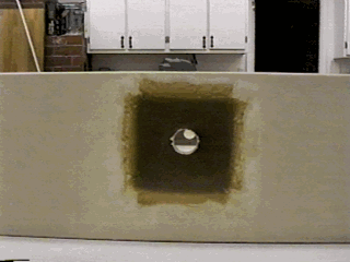
Figure -2, 4"x4", 8 ply lay-up shown on wing spar.
MAIN
SPAR AND OUTBOARD SPAR PRE ASSEMBLY
NOTE: Part of this procedure is also referenced in the fuselage assembly
instructions, since you may have elected to start the fuselage assembly before
the wing operations. The assembly of the spar sections is required before
either installing the spar center section into the fuselage, or using the
outer spar assemblies in building up the wing. Since this operation requires
a fairly large flat area for fitting the outer sections to the inner section,
it may be a good idea to complete this operation prior to starting the fuselage,
or setting up for the wing.
-
Locate the center spar section (C13) and the center spar section close-out
(C15).
-
Remove all peel ply and other debris, and trim the flanges of the close-out
such that you can get a good fit when the parts are assembled.
-
The end section of the close-out should lay flat against the spar web, so
trim off any flange like lip on this flat portion and trim the balance of
the flange (top and bottom of the "U" shape) to roughly 2 inches wide. (measure
2 inches up from the spar face in several locations and mark. Using the marks
and a straight edge, draw a trimming guide line) Reference figure 7-5.
-
Check the inner surfaces of the spar section flanges, and grind down any
lumpiness in the glass on this surface that may have built up due to overlaps
in the glass lamination You may grind through one or two layers of glass
in this area without compromising any structure, but DO NOT grind
into any of the black carbon fiber in this flange.
-
Test fit the close-out section with the spar section, and mark areas which
must be sanded away from the close-out insert before re assembly. If the
fit-up is too tight, heavy sanding may be required and is permissible on
the close out insert molded part, but not the carbon fiber spar cap section.
A snug fit is desired, but not so tight that it distorts the flanges of the
primary spar section, nor displaces all of the adhesive from the joint areas.
-
Transfer the location of the pre drilled holes in the center section to the
close-out and cut them out. Do this as accurately as possible, especially
at the BL 46 holes where the bushing will be bonded into both parts, however,
even these holes should be a little oversize to allow bushing insertion cleanly
into the factory drilled holes without misalignment. Some judicious filing
or sanding may be required to allow free assembly of the bushing without
wiping off all the bonding adhesive. The BL 22 holes in the close out side
will have to be expanded to a bit over 1.5 inch diameter since the large
diameter section of the bushing will be in this section.
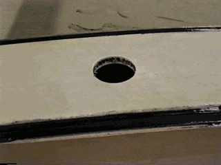
Figure -3, BL-22, 1-1/2" bushing hole in close-out.
-
Note the contacting surfaces of the two parts where they will be bonded (
this will be the two flat end pieces and the flanges of the close-out) and
roughen and clean to prepare for bonding. Use the CS 18A and CS 19 bushings
as an alignment aid in fitting the parts together, and verify that the assembled
thickness will be 3 inches from face of spar to face of close-out.
-
Bond the assembly together using Hysol adhesive (mixed per instructions)
, be sure to clean up any excess adhesive, particularly in the holes where
the bushings must be placed, and any other external surfaces where fit up
may be compromised.
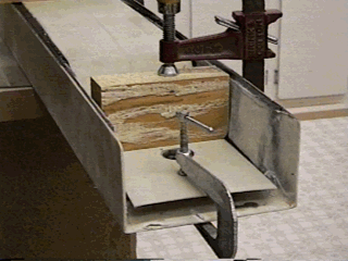
Figure -4 Center spar insert glued and clamped
CHECK FOR TWIST
-
The basic spar section is incredibly strong in bending, but surprisingly
flexible in torsion until the close-out section is bonded into place forming
the "box" section. This is your last chance - before the bond line cures,
apply a level or other straight edge on the primary spar section,
web surface, at each end and sight for any twist. If any twist is noted clamp
the assembly to a solid surface and use the clamps and shims to eliminate
any evidence of twist and allow to cure. Apply a visual twist test to any
assembly which is being "closed out" .
-
Repeat these steps for the outer spar sections (C-14 R & L) and close-outs
(C-16 R&L). The outboard spars use the CS-18 and CS-19 bushings. The
inboard mounting hole on each outer spar, locates the 22 inch butt line when
aligned with the main spar mounting holes and measured from the main spar
center line. When installing the close-out to these spars, set the distance
to the outer angle of the close-out to 25.5 inches or 3.5 inches from
the hole as in figure 7-5.
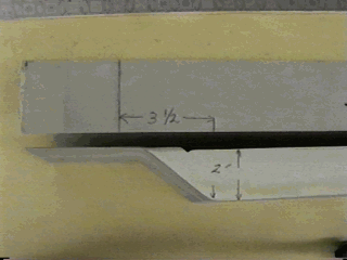
Figure -5, Outboard wing spar close-out location.
-
Remember to hold assembled spar thickness to 3 inches using the same techniques
as with the main spar.
-
Locating the spar insert using the BL-22 references will result in some overhang
with the end of the spar. Trim the insert even with the end of the spar.
-
For easy reference in future operations, mark the spars left and right (confirm,
using the factory stamp on the part), and also mark the top.
Install Bushings
-
The bushings (CS-18, CS-18A and CS-19) are made a little long to allow for
variations in lay-up thickness. The faces of the small diameter end of the
bushings should not protrude above the spar surface, slightly (as much as
1/16 in.) below the surface is desired. Carefully machine or file these ends
to this condition if they are too long. Prepare all bushings at one time
and mark them for reference to be assured that you will get them back into
the right location for bonding. Reference figure 7-6.
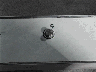
Figure -6, Bushing marked "G" in "G" hole. Spars bolted together.
-
Locate the AN-9 spar bolts and wax them liberally with a good paste
carnuba floor wax so they won’t be bonded into place.
-
Tape the facing spar surfaces with clear tape and carefully cut the holes
for the bolts through the tape.
-
Prepare Two shims of approximately .025 inches thick (cardboard will work)
to place at BL-22 bolt holes. These shims are to match the 8 ply lay-up at
BL-46. Make sure enough shim has been added. Measure the distance between
the spars at each of the bolts and adjust the shim thickness until they are
equal.
-
On a flat surface, set blocks beneath the center section to provide bolt
end clearance (so a wrench will fit), and at least two blocks, one at the
outer wing spar mid section and one at the end.
-
The outer spar sections should both be joined at the same time if you have
sufficient room (one side at a time is permissible so long as the set up
is straight and flat and the dihedral verified uniform by separate measurement).
-
Glue the bushings in place with Hysol adhesive, cleaning up prior to clamping,
to provide for successful disassembly. Do not worry about the fact that the
large (1.5 inch) (diameter section of the bushings protrude from the surface,
and do not be concerned with bonding in this area. After the two outer spars
are bolted in place verify that no twisting has been induced, and use a string
between spar tips to verify that the dihedral angel is the same on both sides
the bushings can move slightly in their bores before the adhesive sets up
so loosen the bolts and make any required adjustments promptly before the
adhesive starts to cure. Support the spar sections in their proper position
during the curing even after the bolts have been tightened.
-
When the adhesive is cured, remove bolts and disassemble the assembly. Clean
up excess adhesive, and fill the gap around the protruding 1.5 inch diameter
bushing end with MICRO/EPOXY paste mix at this time.