Tri-R Technologies TR-4
BUILDER'S MANUAL
This Builder's Manual is NOT the official manual as published by TRI-R Technologies.
FINAL ASSEMBLY
Quick Links to Final Assembly
Sub-Sections:
WING
INITIAL ATTACH
WING
INCIDENCE CHECK AND SET
UPPER
WING ROOT FAIRINGS
SETTING
FLAP POSITION
ADJUST
AILERON RIGGING
CASTERING
NOSE GEAR ASSEMBLY
MOUNTING
THE WHEEL
CASTERING
NOSE WHEEL YOKE
OPTIONAL WHEEL FAIRING ASSEMBLY
Note: Wheel fairings are not provided in the standard Cruiser kit. These instructions are provided for those builders who purchase the fairing kit at extra charge.
MAIN
GEAR FAIRINGS
NOSEGEAR
FAIRING
One of the most important operations in the final assembly is the attachment and line up of the wing panels. For this operation it is recommended that you provide a clear open area sufficient for mounting both wing halves at the same time, and that it be reasonably level and provide adequate working space around the perimeter. Since you will be attaching and removing the wing sections several times, it is suggested that you determine the minimum length of main spar bolt for just s few turns of thread engagement, and washer the head end of the bolts to this limited length. This will minimize wear and tear on the locking section of the secured nut, and give you a better feel for the tightening forces clamping the spars together.
It would be a good idea to level the fuselage assembly in both axis at this time.
Check the spar faces to assure yourself that the BID pads have been added to the main spar mating surfaces to avoid unintended "sweeping" of the wing angle. It is acceptable to have installed the BUTT LINE 46 pads on either the wing spar section or the center spar outer face – just so the total build up is the same at both butt lines such that the assembly has been "shimmed" straight.
Check the mating surfaces (rear face) of the center spar for angle at all four of the bolting positions (left and right butt lines 22 and 46). If the spar has been properly assembled with no twist, all these faces should be roughly 3 degrees from vertical (tilting aft) and parallel within about a half degree. Any small amount of deviation from the other surfaces (twist), can be corrected by adding some staggered plies of BID, and faring the surface with FLOX.
Use considerable care when sliding the open end of the wing on the stub spar extending from the fuselage side. You have incredible leverage at the wing tip, and lifting or lowering the tip excessively could easily tear the wing skins loose in this area. Some trimming will be required at the end of the spars to allow full insertion of the wing sections. Strive for roughly ¼ inch clearance between the end of any spar, and the fuselage outer skin, or any other potential interference point.
The procedure that has worked best for us is to start the inboard bolt through both spar bushings first, and the carefully raise and lower the tip, and shaking it slightly to start the outer bolt. Snug these bolts up just enough to eliminate perceptible looseness between spar faces.
Repeat this process for the other wing half.
The nominal wing incidence angle relative to the zero waterline is a positive 3 degrees (leading edge higher than trailing edge). However, more important than this exact value is that the angle of the two wing sides be the same. If you are up or down one degree on the absolute incidence angle it only really changes the flying "deck" angle slightly with a small effect on drag and trim conditions. However, if you have this kind of variation between sides, you can induce a large "roll" input, which would have a very negative impact on control limits and out of trim forces.
Carefully recheck the level of the fuselage in both directions. The general rule of thumb for this level check is to use the cockpit edges.
If you do not have an airfoil template gage with the three degree angle reference fabricated, make one up at this time. If you have lost or damaged the full scale airfoil drawing, contact the factory, and we will send you a new one. This template should be made of sufficiently rigid and durable material (plywood, masonite, etc) such that it can be placed on the wing upper surface and support a level on the 3 degree reference line.
Check both sides in their present bolted on condition, and verify that you can displace them to the referenced 3 degree position. As mentioned before – SAME angle is more important than exact angle, and if on panel cannot be exactly pushed to this position determine the angle that can be attained on both panels. If this angle is within 1 degree of standard, record this angle and make them the same on both sides.
There should be some separation between adjacent faces on the rear spar (about ¼ inch). DO NOT clamp that spacing closed. Make up a free fitting shim ( of plywood, Masonite, fiberglass, or other material with good compressive properties that you can drill though in a subsequent step)of the appropriate thickness and "tack" bond it to one of the surfaces.
Line up, and secure the position for the proper incidence angle, and pilot drill (clearance for a #10 bolt) through the two spar sections. Locate this hole inboard of the flap bearing hanger, and roughly centered in the two parts. Make sure there is sufficient edge clearance for the aluminum "hat" shaped bushings which will be subsequently installed . Also, be sure to verify that the position of these holes will not be blocked by the flap actuation torque tube.
Secure the first side with a snugged up #10 bolt and nut, and recheck angles before drilling the other wing panel in a similar fashion.
Locate and select the 4 bushings to be installed and enlarge the holes to accept these bushings. Verify that the bushings are not too long, such as to protrude from the mating surfaces, and proclude proper clamping. (trim if required)
Coat the bushing surface to be bonded with Hy-Sol or FLOX adhesive. Lightly oil the bolts to be used, and separate the two spar faces and the selected shim in the local area with waxed paper or plastic to avoid inadvertent bonding of these parts.
Install the bushings using the proper diameter bolts (5/16 in), and lightly clamp in place (use a non locking nut at this time, and just a bit more than finger tight). Confirm that the bushing flanges are down snug on the part surface.
Locate and drill the ½ inch diameter holes through the rear spar of the wing, and the fuselage stub spar, for the rear spar bushings. This also should be drilled in conservative steps to provide a clean accurate hole. Again use ½ inch hardware store bolts for temporary alignment.
With the wing panels temporarily installed on both sides, fit the flaps in place, and position them in the "up" position by using the airfoil template to determine true position.
Test fit the fairing moldings on both sides. Note the fit to the fuselage sides and have someone sight from the front and rear to assure that they will be the same on both sides. You should have a minimum bond area of about ¾ inch, If trimming some of the edge makes a better fit, this may be done so long as this minimum bond width is maintained.
Drill some small pilot holes (about 1/16 in for screws or proper diameter For clecos) through the fairing flange and into the fuselage skin. Temporarily attach with small sheet metal screws or clecos. Mark the upper edge of the intended bond area.
Fit up the lower trailing edge section of the fairing, observing and clamping the trailing edge joint. If the outer flange on this part is adding too much thickness above the flap surface, it is permissible to cut off this flange, and recreate it facing inward with about 2 or 3 ply BID.
Also mark the bond areas for this lower fairing section.
Remove the fairings and thoroughly scuff the bond areas on both parts with coarse (# 36 or similar) sand paper.
Mix a batch of FLOX to a pasty (adhesive like) consistency and coat both surfaces to be bonded (inner surface of the fairing and the fuselage side).
Secure fairings with sufficient screws or clecos to make a smooth edge with the fuselage skin. Clean off surplus adhesive which has squeezed out, but leave a fillet at the transition edge for sanding later. It might be a good idea to tape or otherwise secure the other edge on the upper wing surface to avoid buckles and waves. If a severe buckle is evident, it is possible to slit the edge, place plastic beneath it and glass tape the cut.
After the adhesive cures sufficiently, remove the screws and/or clecos, and clean up the edges. The trailing edge joint between the upper and lower fairing sections is subject to vibration, and is a difficult joining surface. A wrap of BID tape (or locally procured lightweight glass cloth) can be a "belt and suspenders" treatment in this area.
If the small plastic square that rides in the flap actuation "track" is deliberately drilled slightly off center, it can be a possible adjustment mechanism to assure symmetrical flap position. A side offset of roughly .020 in. and a vertical offset of .040 in. will give you up to .08 inch of corrective travel if required in .02 in, increments by relative rotational position of the blocks on each side. More severe corrections can be obtained by greater offsets, but the actuation arm may interfere with the sides of the "track."
When the two flap sides are equal, it is a simple matter to adjust linkage length to place the flaps in proper position for normal flight (as checked by the airfoil template."
Actuate the flaps through full travel, and clear any interference problems and assure free and positive operation.
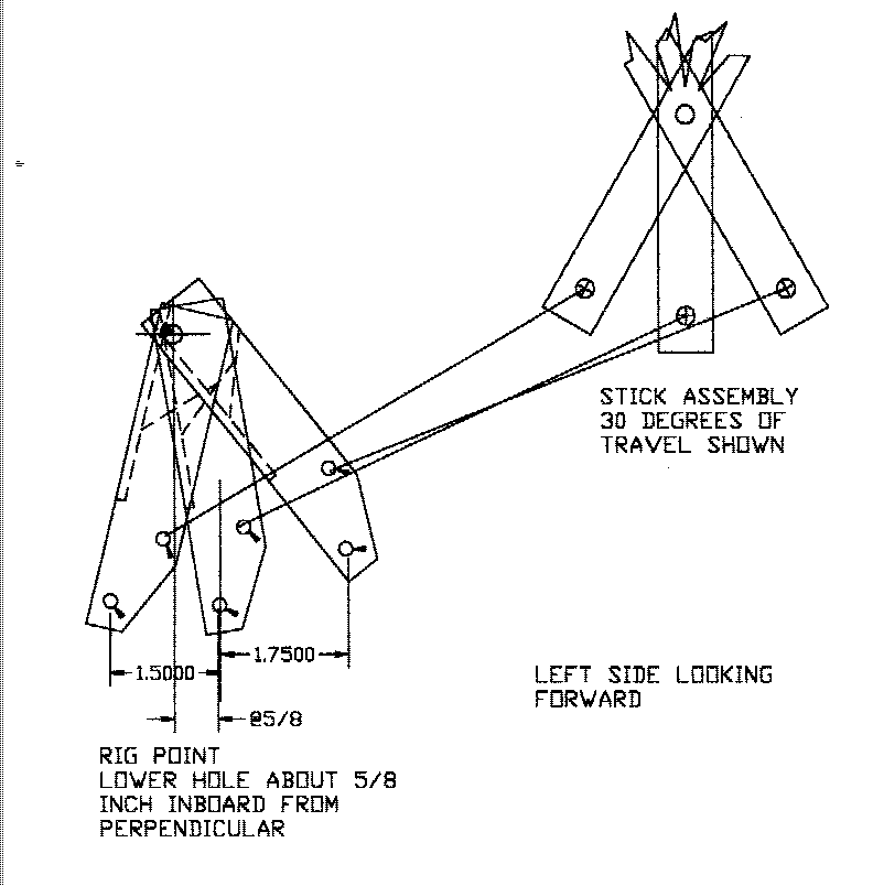
Verify that the sticks are centered, and the aileron idler bellcranks in on the fuselage wall are in the proper position (these positions determine the aileron differential and are important for proper flight characteristics, and "feel".)
The original drawing of the control linkage in the fuselage section was in error, and if it has not been previously corrected make these changes. The offset in the aileron idler link is intended to be an element in the linkage system to increase aileron differential to reduce adverse yaw, an slightly reduce aileron actuation forces – but I drew it in backwards, which would actually counter the differential effect of the aileron bell crank. To correct this, reverse the location of the idlers – put the one shown on the right side over on the left side etc. The new rigging angles are set by swinging the link inboard such that the lower hole is roughly 5/8 inch inboard of perpendicular (ref sketch).
For those of you that have sized the push tube going out to the wing – this will result in almost the exact same length setting. The link to the control stick (made from ¼ inch threaded rod) will now be shorter, and may have to be cut (measure twice and cut once). The rod end of the short rod from the stick, should be mounted on the forward face of the link, and the rod end from the wing on the aft face (remember to use the large area washers to capture the overhung side of the rod end). The offset to the two faces induces a small amount of torque into the arm, but it provides better line up and avoids interference between the two rod ends Observe the rise and fall of the tube in the leading edge of the wing, and assure that there is no interference to travel. The link position may have to be adjusted a bit rearward if possible, or a spacer beneath the rod end at the link, to move the tube a bit aft where there is more vertical room.
The enclosed picture shows the relationship of the aileron idler link, and the control stick on the left (pilot’s side) looking forward. The 30 degree travel shown is the approximate maximum allowed by the stick travel stops. In most installations the counter weights on the aileron will limit the travel to roughly 8 or 9 degrees in the downward direction and about 13 or 14 degrees upward. Some minor increase in travel can be provided by cutting away the inner surface of the skin sandwich panel in a local area, but the above values should be sufficient,
Adjust the rod between the ailerons and their respective outer bellcranks such that the long arm of the aileron bell crank is parallel to the direction of flight when the ailerons are in neutral.
Adjust the aileron rod lengths to satisfy these conditions at rest. The ailerons will "fly" up just a little under flight loads, and that is just fine.
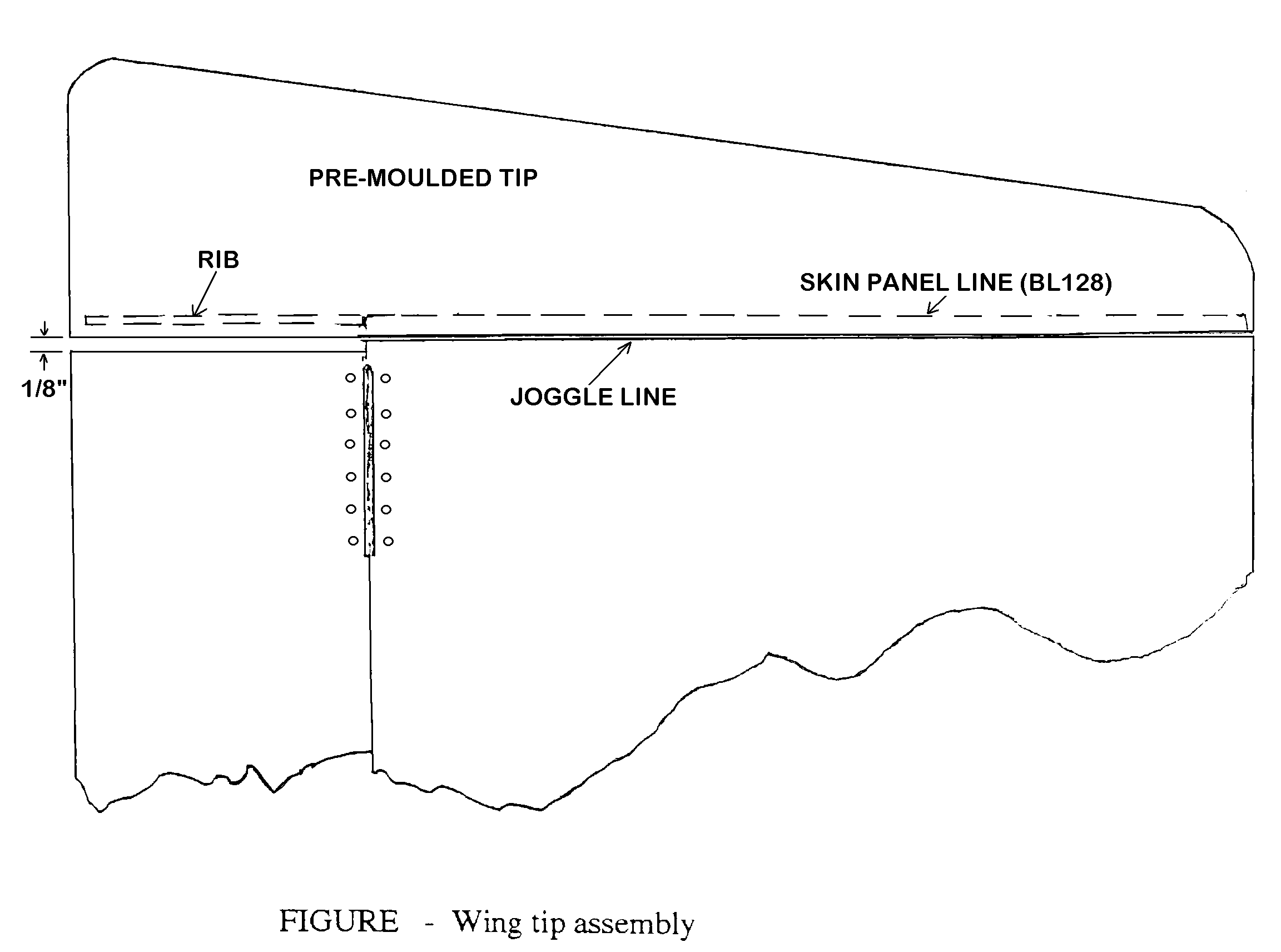
Prepare the pre-molded polyester and fiberglass wing tips for installation. Cut two trailing edge ribs of ¼ foam using the template supplied. Install each rib about 7/8 inch into its tip so as to allow the tip to slide over the joggle end of the skin. The rib should butt up against the aft spar face. Apply one layer of BID to each rib to keep them in place and help them hold shape. Check fit the tips onto the wing panels. The joggles on the skins help make them fit flush.
The wing tips are fabricated with polyester resin, and it is possible that some distortion may have been introduced during shipping or storage. In some cases it may be necessary to slit the trailing edge of the wing tip molding to properly align the tip. Make numerous dry installations to assure proper alignment before bonding
If everything is okay use a thin mixture of resin and flox to bond the wing tips permanently in place. Be sure to tape or screw the tips in position so they don’t shift while the flox is curing. Stand back and make sure they are properly aligned before cure; a "bent" wing tip would really be an eyesore, and could adversely impact the trim of the aircraft
An alternate method of attaching the tips is to leave them removable. If this is desired attach each tip with equally spaced AN507-832-8 csnk.. machine screws ( at least six top and six bottom) and K 1000-832 anchor nuts. The alternate installation hardware is not provided.