Tri-R Technologies
TR-4
BUILDER'S
MANUAL
This Builder's Manual is NOT the official manual
as published by TRI-R Technologies.
FINAL
ASSEMBLY
Quick Links to Final Assembly
Sub-Sections:
WING
INITIAL ATTACH
WING
INCIDENCE CHECK AND SET
UPPER
WING ROOT FAIRINGS
SETTING
FLAP POSITION
ADJUST
AILERON RIGGING
CASTERING
NOSE GEAR ASSEMBLY
MOUNTING
THE WHEEL
CASTERING
NOSE WHEEL YOKE
FUEL
SYSTEM
WING
TIP INSTALLATION
OPTIONAL
WHEEL FAIRING ASSEMBLY
Note: Wheel fairings are not provided in the standard Cruiser kit. These
instructions are provided for those builders who purchase the fairing kit
at extra charge.
MAIN
GEAR FAIRINGS
NOSEGEAR
FAIRING
CASTERING NOSE GEAR
ASSEMBLY
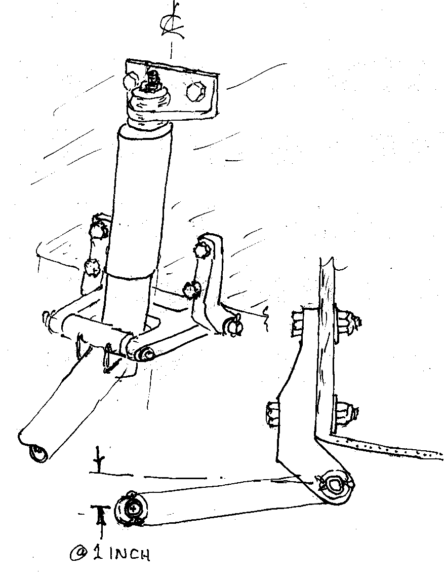 Many of the four place kits
are now being provided with a castering version of the nose gear, much like
the very successful new two place gear. These gear assemblies are shipped
almost completely assembled and ready to install. The basic approach is to
use the assembly as a template for drilling the required mounting holes through
the fire wall. Place the nose gear assembly roughly in place on the firewall
as shown in the attached sketch.
Many of the four place kits
are now being provided with a castering version of the nose gear, much like
the very successful new two place gear. These gear assemblies are shipped
almost completely assembled and ready to install. The basic approach is to
use the assembly as a template for drilling the required mounting holes through
the fire wall. Place the nose gear assembly roughly in place on the firewall
as shown in the attached sketch.
Center the top bracket at roughly the expected height, and secure with tape
or other temporary means. Set the gear leg vertical to fuselage centerline,
and push the linkage and "L" shaped brackets up into position. Raise these
legs up until one or both are limited by the inner "bend" radius contacting
the lower edge of the firewall. Both brackets should be at roughly the same
height, but the position of the assembled linkage is more important than
for both to contact the bottom edge of the firewall simultaneously . However
if there is a great difference side to side recheck your positioning before
drilling any holes, and contact the factory if you cannot resolve this problem.
Verify where the bolt holes will break through the back of the firewall and
ensure that clearance exists for a generous washer, and no other components
will be damaged when the holes are drilled.
When you are assured of this positioning drill clearance holes and install
appropriate 5/16 bolts nuts and washers. To temporarily secure this part
of the assembly (the top bracket should still be only temporally retained
in position)
With the fuselage supported, and no weight on the gear leg, the upper bracket
should be positioned vertically such that the outer end of the lower "H"
link is roughly one inch below horizontal. Check the back side of the firewall
where these upper bolt holes will come through to assure that fiberglass
stiffening lay-ups are present. Also check the location of the wheel when
the assembly is suspended in this position to estimate the static height
of the front of the airplane. With the static load we would expect roughly
one inch of strut compression and about a half inch of tire deflection. Under
static conditions the aircraft should sit just a few degrees nose high. If
either of these conditions appear seriously amiss we would suggest you contact
the factory
When the vertical position is established use the bracket as a template and
drill clearance for and install two 3/8 inch bolts nuts and washers to attach
the top bracket
MOUNTING THE WHEEL
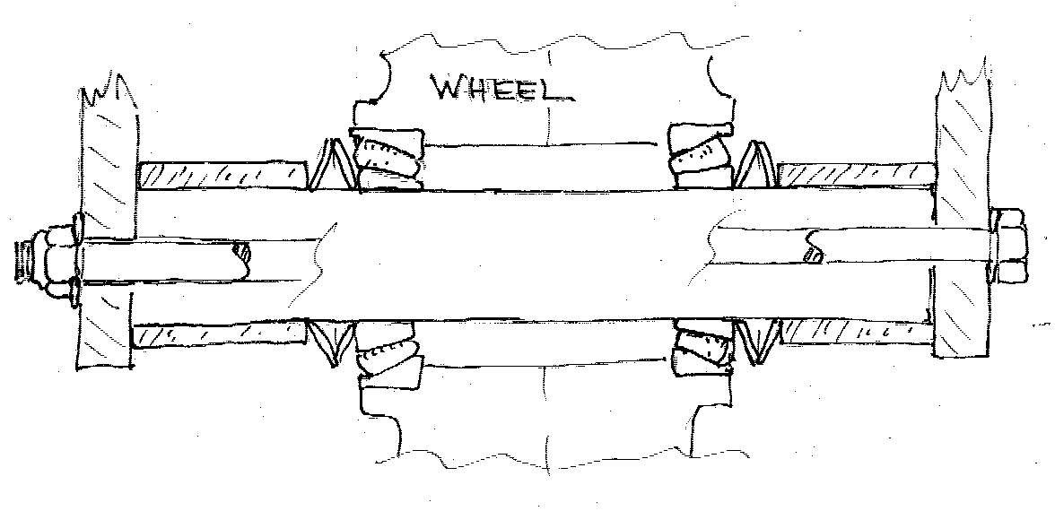 The wheel can be mounted at
any time, but may be advantageous to delay it to reduce the weight of the
assembly during handling and mounting. The wheels being shipped at this time
employ tapered roller bearings which require a preload for proper operation.
Four Belleville spring washers are used in the installation to provide an
adjustable preload. Two washers are installed on each side of the wheel "flare
to flare" as shown on the sketch. A tubular spacer is also installed on each
side as shown and the center bolt tightened to compress the spring washers
and load the bearings. Torquing the bolt all the way down may provide excessive
preload for too much friction and premature bearing failure.
The wheel can be mounted at
any time, but may be advantageous to delay it to reduce the weight of the
assembly during handling and mounting. The wheels being shipped at this time
employ tapered roller bearings which require a preload for proper operation.
Four Belleville spring washers are used in the installation to provide an
adjustable preload. Two washers are installed on each side of the wheel "flare
to flare" as shown on the sketch. A tubular spacer is also installed on each
side as shown and the center bolt tightened to compress the spring washers
and load the bearings. Torquing the bolt all the way down may provide excessive
preload for too much friction and premature bearing failure.
The rubber seal on the bearing may mask the proper preload, so lubricate
this seal and rotate the wheel numerous times to get the preload which secure
the inner race from rotating on the axle but not overload the bearing.
CASTERING NOSE WHEEL
YOKE
This item should come installed but if it is disassembled for any reason
note the relationship of the spring (Bellvile), and plain washers for proper
reassembly.
Check the pivot friction regularly, particularly during early operation as
it breaks in. It should take a fairly vigorous push (about 15 to 20 lbs.)
at the axle location to pivot the assembly. If shimmy is noted during operation,
check the tension in this assembly to assure that friction is present for
damping. Friction is increased by tightening the castellated nut (be sure
and replace cotter key).
Swiveling of the nose wheel yoke is limited by the three roll pins (two on
the yoke, and one on the gear leg). Some early gears were shipped with 3/16
inch diameter pins, which have had durability problems. If this is the case
on your assembly, it is suggested that they be removed with a vice-grip or
similar tool, and ¼ inch diameter pins fitted.
The aluminum yoke sides provide a wide choice of locations for drilled and
tapped holes for fastening the front wheel pant. The drag of an unfaired
nose wheel is very high so close attention to this area will help in cruise
speed and fuel economy. The installation of optional wheel fairings is covered
in a later section.