Tri-R Technologies TR-4
BUILDER'S MANUAL
This Builder's Manual is NOT the official manual as published by TRI-R Technologies.
FINAL ASSEMBLY
Quick Links to Final Assembly
Sub-Sections:
WING
INITIAL
ATTACH
WING
INCIDENCE CHECK AND
SET
UPPER
WING ROOT
FAIRINGS
SETTING
FLAP
POSITION
ADJUST
AILERON RIGGING
CASTERING
NOSE GEAR
ASSEMBLY
MOUNTING
THE
WHEEL
CASTERING
NOSE WHEEL YOKE
OPTIONAL WHEEL FAIRING ASSEMBLY
Note: Wheel fairings are not provided in the standard Cruiser kit. These instructions are provided for those builders who purchase the fairing kit at extra charge.
MAIN
GEAR
FAIRINGS
NOSEGEAR
FAIRING
OPTIONAL WHEEL FAIRING ASSEMBLY
Note: Wheel fairings are not provided in the standard Cruiser kit. These instructions are provided for those builders who purchase the fairing kit at extra charge.
With an aircraft of the speed potential of the Cruiser, the wheel fairings become a very valuable option, adding 5 to 10 mph to the cruise speed at the same fuel burn. However, a poorly installed set of fairings can quickly become a greater bother than a benefit.
Carefully trim and fit the wheel fairing to the wheel, centering it to avoid rubbing on any surface, and provide enough wheel protrusion below the faking to suit the type of landing surface where you will be operating. There should be enough wheel showing such that even with a flat tire and in landing attitude, the faking will not strike the surface. Refer to the pictures on the next page and fabricate a bracket of aluminum sheet at least .080 thick as shown to retain the inner side of the wheel fairing. (It may be advantageous to make the bracket flat rather than as shown; in this case the bracket will clamp between the axle and the gear leg.) Use the upper two axle bolts for attachment, and drill and tap the gear leg #10-32 for two additional bolts if desired for added rigidity, secure to the fiberglass wheel fairing with two #10-32 bolts at each end. Verify location and length of bolts for clearance to the wheel and tire. Nut plates can be added to the fiberglass part for ease in assembly and disassembly
For support to the outer side of the wheel faking, drill and tap the end of the axle above the centerline to avoid the cotter pin hole. A ¼ inch threaded rod is suggested for this support. Use a jam nut to secure it tightly to the axle, and another nut to space out the fairing shell. Use an area washer inside the surface of the shell, and a self locking nut on the outside of the faking. An area washer here would ad d structural support, but is probably not required. Trim excess rod for a neat looking job with minimum air drag. Supported on both sides in this manner, the fairing should almost be secure enough to stand on.
Trim and fit the back cover of the fairing assembly. Position and drill 6 holes for securing it to the main fairing body. Verify the length and position of the securing bolts such that they will not rub on the wheel or tire. Install #8-32 nut plates at these locations and bolt into place with #8-32 screws. Again verify that the screws are not excessive length and will not drag on the wheel.
Make note of the complexity of assembly and disassembly and decide if you are going to provide a hole for tire inflation. If so cut it before painting. Electrical supply houses frequently sell plated metal cover plugs with spring fingers for closing access holes in electrical equipment., and you might consider these as an option.
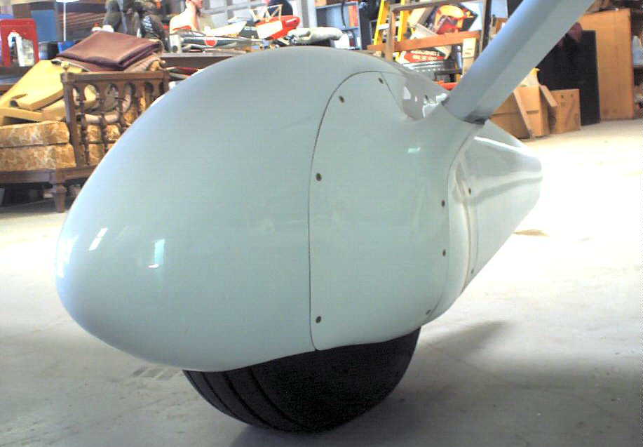
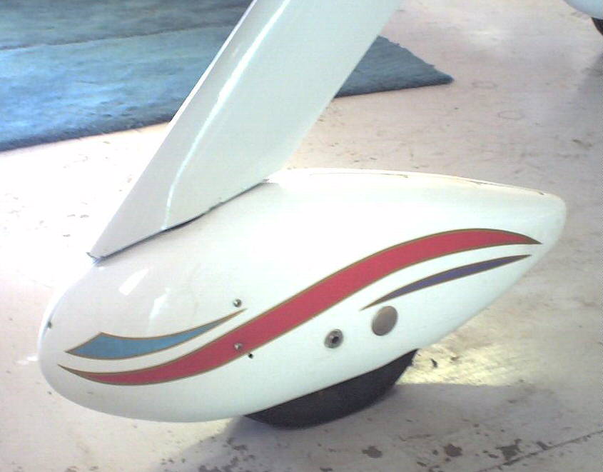
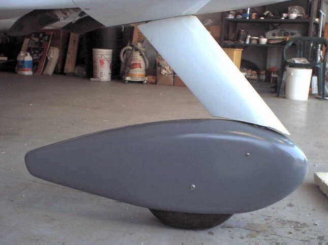
The nose gear fairing is equally important, and presents a slightly different challenge. This gear must be free to swivel to permit steering on the ground, and the interface with the gear leg fairing is an extra place of concern during the installation.
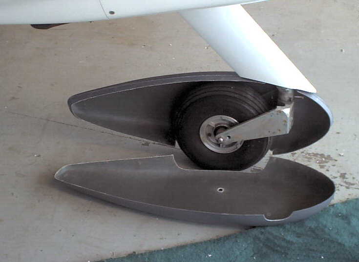
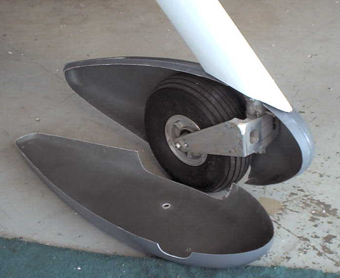
The nose gear fairing comes as a two piece assembly split roughly in the middle lengthwise of the section. Position the half with the positive overlap (right side), locating the desired placement of the wheel axle and the orientation of the fairing to the ground level. The wheel fairing halves may have to be drilled to clear the ends of the axle. Be sure you have verified the desired position before drilling these holes Also note the location of the gear leg pivoting action to assure proper steering of the wheel without interference with the gear leg fairing (it might be prudent to test fit this fairing at the same time). locate one attach bolt as far forward as practical on the flat surface on the side of the "shoe" (pivoting wheel fork). A shaped "shim" of Bondo or dry micro can be used to match and space the inner surface of the wheel fairing to the side of this "shoe". Center the fairing longitudinal seam with the centerline of the tire during this fitting. The material of the side of the "shoe " can be tapped for the attaching thread - we suggest a #10-32. Another attach bolt and "shim" should be provided back near the axle (be sure that the bolts extending through this surface will not rub on the tire or wheel -watch both positioning and trimmed length for this). If the attachment holes are tapped as suggested rather than using self locking nut plates, remember to use Loktite or similar thread securing compound in final assembly.
Temporarily attach the other half, and locate a similar pair of bolts and "shims" in symmetrical locations. Double check at each step to assure that the proper alignment is being maintained, and trim away or add shimming material as required.
As before, decide if you are going to provide a hole for tire inflation, and if so locate in the desired position and cut hole before painting.
|
 |
New Style - Longer Nose Wheel Fairing
 |
 |
 |